
The uncertainty of this gun being cocked and staying cocked is a problem. In releasing valve guns such as the GSD models the different pressure existing on either side of the valve plug in the cocked gun keeps it firmly closed as high internal air pressure is trying to push the valve plug down the inner barrel, the opposite direction to that in which it can move in order to open up and thus shoot the spear. In a "Zelinka" the releasing valve is mechanically held shut by the trigger mechanism's catch element that blocks the mobile inner barrel (which is actually the valve body) from moving as air transfers across into the outer pressure reservoir during muzzle loading via a completely separate, expanding rubber ring type valve that does not involve the releasing valve opening at all. So provided that these valves don't leak the gun will stay cocked. If they do leak then the air flow is so restricted that the spear only moves slowly out of the gun. But on a balanced valve gun, such as the one shown in the preceding diagrams, you will not be so sure as any air leak via the rear sealing ring (which traverses the inner barrel windows or side ports during operation and therefore risks damage!) will blow the releasing valve right open, it will not just let a trickle of air through and send the spear slowly back against your loading effort when the gun failed to cock properly. Instead it will shoot with its full force, so you would want to get your loading hand out of the way of the muzzle very quickly. Of course you always do if you don't want to be shot through the hand with any muzzle loading and simultaneous cocking speargun, but here it will be likely to happen with zero warning. Basically this is because any air leak in the valve powers the releasing valve body to fully open up and completely expose the inner barrel side ports, it will not just gradually lose air through a constant small gap. For that reason commercial production of this type of design would be a risk that most speargun manufacturers would choose to avoid.
Guest viewing is limited
- You have a limited number of page views remaining
- 4 guest views remaining
- Register now to remove this limitation
-
Welcome to the DeeperBlue.com Forums, the largest online community dedicated to Freediving, Scuba Diving and Spearfishing. To gain full access to the DeeperBlue.com Forums you must register for a free account. As a registered member you will be able to:
- Join over 44,280+ fellow diving enthusiasts from around the world on this forum
- Participate in and browse from over 516,210+ posts.
- Communicate privately with other divers from around the world.
- Post your own photos or view from 7,441+ user submitted images.
- All this and much more...
You can gain access to all this absolutely free when you register for an account, so sign up today!
Idea for a pneumatic gun
- Thread startertromic
- Start date
Thread Status: Hello
, There was no answer in this thread for more than 60 days.
It can take a long time to get an up-to-date response or contact with relevant users.
It can take a long time to get an up-to-date response or contact with relevant users.
Love pneumatic guns but spearfish in shallow fresh water going to salt water and deeper how does this affect pneumatic guns
Answered via a private message.
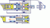
This diagram shows how the balanced valve speargun system works. Once the compressed air flows into the inner barrel (orange arrows) it pushes the blue tubular valve open. The trigger moves the blue tubular valve forwards until its rearmost "O" ring seal passes into the side port or window, then the pressure build-up behind the valve does the rest and shoves the tubular valve body forwards. Some air will leak between the blue tubular valve and grey "top hat" adjacent sliding surfaces, but once they fully separate the air will flow through the blue tubular valve's bore. Any air leak on that rear "O" ring seal will emulate you pulling the trigger! Tight "O" rings on the blue tubular valve would ameliorate the misfire situation, but would then throttle the shot; unfortunately you cannot have it both ways!
Attachments
Maybe safer solution. Before laoding trigger must be pulled so green part would be near horizontal. Spring creates a force to push the trigger pin deeper, left. This is just idea so some details missing on drawing.
Parasitic air serves to push the trigger pin out, after the green part is in position as on picture. If the trigger would become harder to pull that might mean that the O-ring is leaking air. I believe this might work and be safe. Only problem is where to put the valve for pumping air into the gun.

Parasitic air serves to push the trigger pin out, after the green part is in position as on picture. If the trigger would become harder to pull that might mean that the O-ring is leaking air. I believe this might work and be safe. Only problem is where to put the valve for pumping air into the gun.

Last edited:
Maybe safer solution. Before laoding trigger must be pulled so green part would be near horizontal. Spring creates a force to push the trigger pin deeper, left. This is just idea so some details missing on drawing.
Parasitic air serves to push the trigger pin out, after the green part is in position as on picture. If the trigger would become harder to pull that might mean that the O-ring is leaking air. I believe this might work and be safe. Only problem is where to put the valve for pumping air into the gun.
Air could be pumped into the gun using a collapsing ring valve positioned anywhere along the outer reservoir, such as is used in the "RPS-3" and many other Russian pneumatic/hydropneumatic spearguns. You will already be familiar with these arrangements. The required hand pump has a stirrup fitting that encircles the body of the gun and matches its outlet over the top of the inlet valve port, the "valve" being the wide rubber ring that collapses inwards (in the vicinity of the port) as air flows, then moves back to create the seal once the air inflow stops. That part is easy, but this design is still very problematic as it is the speargun equivalent of pushing someone over a cliff. There is no unblocking action being used, instead the valve is opened in the same direction that the air moves to power the shot. While the flexible rear part of the yellow coloured piston being plugged by the longitudinal pin is an interesting idea, the flexing required of that part, which must be side-slotted to enable it to collapse and escape from the purple/lavender coloured rear holder, will mean that the rear of the piston will eventually break off, yet there would be no way of knowing when that will occur. Spearguns are already dangerous weapons, there is no need to make them even more dangerous, especially with muzzle loading and simultaneous cocking guns!

The cross-hatched side valve will be unreliable in sealing as it approaches at an angle to its seat. The inspiration is a flute valve, but they don't have to be absolutely air-tight in a musical instrument which operates at low air pressures. If the mechanism was made to be as accurate as the drawing shows then the gun may not even shoot as there would be no appreciable force differential from the high pressure air acting on the two piston seals once the side valve opens to cause the piston to move forwards. The front seal diameter on the piston is larger than the rear one to create a force differential, but the cross-sectional areas at the seal peripheries are very small, being rings, as are the gaps around them that can be filled with pressurized air. This may cause slow opening of the piston which is itself a valve.
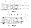
Here is a GSD patent that may interest you, especially after your previous post on the flexible tail piston being expanded with a longitudinal pin. It may have been used on the "Pull" version of the GSD guns which looks otherwise identical to the preceding valve-operated models. The trigger mechanism still makes use of the "Dynamic/Katiuscia" lever and crank system, but has substituted the piston valve body with a spike on a piston that expands the bulbous piston tail. Not sure how reliable this system would be and I have never had a "Pull" model to dismantle, so I am not even sure if it was ever used. The bulbous piston tail is split with slots in a cross shape looking from the rear so that it can expand when that spike enters it. The port that it squeezes through is made from "Delrin" or some similar material and has a larger hole in it than the valve operated versions, or that would be my guess, so less throttling of the shot.
Here is a GSD patent that may interest you, especially after your previous post on the flexible tail piston being expanded with a longitudinal pin. It may have been used on the "Pull" version of the GSD guns which looks otherwise identical to the preceding valve-operated models. The trigger mechanism still makes use of the "Dynamic/Katiuscia" lever and crank system, but has substituted the piston valve body with a spike on a piston that expands the bulbous piston tail. Not sure how reliable this system would be and I have never had a "Pull" model to dismantle, so I am not even sure if it was ever used. The bulbous piston tail is split with slots in a cross shape looking from the rear so that it can expand when that spike enters it. The port that it squeezes through is made from "Delrin" or some similar material and has a larger hole in it than the valve operated versions, or that would be my guess, so less throttling of the shot.
Attachments
Last edited:
The cross-hatched side valve will be unreliable in sealing as it approaches at an angle to its seat. The inspiration is a flute valve, but they don't have to be absolutely air-tight in a musical instrument which operates at low air pressures. If the mechanism was made to be as accurate as the drawing shows then the gun may not even shoot as there would be no appreciable force differential from the high pressure air acting on the two piston seals once the side valve opens to cause the piston to move forwards. The front seal diameter on the piston is larger than the rear one to create a force differential, but the cross-sectional areas at the seal peripheries are very small, being rings, as are the gaps around them that can be filled with pressurized air. This may cause slow opening of the piston which is itself a valve.
Here is a GSD patent that may interest you, especially after your previous post on the flexible tail piston being expanded with a longitudinal pin. It may have been used on the "Pull" version of the GSD guns which looks otherwise identical to the preceding valve-operated models. The trigger mechanism still makes use of the "Dynamic/Katiuscia" lever and crank system, but has substituted the piston valve body with a spike on a piston that expands the bulbous piston tail. Not sure how reliable this system would be and I have never had a "Pull" model to dismantle, so I am not even sure if it was ever used.
Interesting GSD design. Mine seems to me to be even more simple. I was thinking to make mushroom piston end of titanium instead of delrin, but that part is just additional safety normally not under strain, except if the right O-ring start leaking the air.
This was a reply on flute valve design on russian forum. Seems to be already tested.
Last edited by a moderator:


How would this be assembled without a join in the inner barrel at the position of the window?
Going back to the earlier design a possibility for the elimination of damage on the rear tubular valve "O" ring would be to widen the bore of the inner barrel to a size where the rear "O" ring just loses contact around its periphery just before it enters the windowed section of the barrel and only returns to the original inner barrel ID after the rear edge of the window is passed. That requires the inner barrel to be bored out for a short section within which the side window (or windows) will be later cut. Doing this counter-boring thins down the inner barrel tube's wall cross-section at that window location unless a longer end cap with the required stepped internal borings contains the side window at its front edge and is of a greater initial wall thickness, thereby replacing the threaded end plug currently proposed, but then requires accurate machining for the now two inner barrel sections to screw together with their bores perfectly aligned. The tubular valve may wobble when traversing the stepped region in the bore diameter as it will then only be held concentric with the bore by the front "O" ring which always stays in the forward section of the barrel. Safety will still be an issue as mentioned earlier.
The "balanced valve" design (keeping that as its name for want of another) would need to be fully tested with deliberately damaged rear "O" rings of varying degree. With a piece torn out of the rubber ring the gun will not cock, so you still have the spear under control of the hand loader as mentioned earlier. The danger is when the gun seems to be cocked and you have removed hand pressure on the loader and then it shoots of its own accord while you are still removing your hand from the muzzle or just afterwards when you do not have full control over the gun as to where it is pointing! Biggest danger then is when the spear departs unexpectedly through the surface of the water and takes an aerial journey to parts unknown at very high velocity, or having hit the end of the shooting line (or the line wraps have not deployed) begins a return journey to the point of origin, you!
"O" rings with slights nicks or cuts are not so inclined to instantly leak, you may get a slight pop and then a whoosh of air as the ring tears further along the direction of the cut. Also damaged "O" rings with slight cuts can rotate or twist on their rubber section width and temporarily clamp up that cut or move it beyond contact with the sealing surface, then untwist and leak as the cut stops being compressed once the ring rebounds in its seat after it has stopped being mechanically pushed during a sliding action in a bore. Misbehaving "O" rings often need a strong magnifier to see the cut, the cut often being created during gun assembly due to a sharp edge or flaw that has escaped previous notice when the "O" ring was slid along a component and into position.
Air leaks through the tubular valve rear "O" ring will push the spear and the piston, a combination which is more massive than the tubular valve, but how soon does the tubular valve follow it and fully open up the windows or ports as air pressure rapidly builds up in the rear of the inner barrel? The clearances between tubular valve and "top hat" pusher are tight to minimize parasitic air volume, so if the gun is not to shoot through the thin annular gap between them the tubular valve has to rapidly part company with the "top hat". This is good during the actual shot, but not so good with an air leak, but how to control it?
This design would be safer (maybe safe enough) if there would be some free space for leaking air from damaged back side O-ring, to follow the red arrow. If after loading the gun the shaft is moving out that would mean the O-ring is slightly damaged. If cocking is imposible damage is serious. That's what I understood from russian forum as explanation why it is safe. What is a chance for some state between this two, which would be dangerous? I like that design. It is simple but is would be not easy to make boring edges safe for O-ring on tabular moving valve.

Regarding my last idea with valve moving outside the barrel that would be easy to make safe for O-rings, but there would be much too parasitic air, especialy with more than one boring for air entering the barrel. Because of parasitic air, with 2 holes of 7 mm piston (11 mm) would move more than 10 cm. Too much! With 1 hole, about 5 - 6 cm. Blue part in contact with piston might be a screw so barrel need not to be made in two parts. ID of moving tabular valve might be 0.1 mm more than the OD of the barrel.
Interesting idea but would not be good. Idea of Valentin is better, but is maybe more difficult to make it well, not to damage the O-ring.
Last edited:


Last edited:

The only way to find out is to make it, just the basic parts as what looks good on paper often has unforseen consequences, you don't need to make the entire gun. I am sure that is what will be happening with the "balanced valve" design. But checking any design out needs more than a few successful shots put through the gun as with everything new in terms of the seals and metal/plastic parts any problems do not always show up in the short term.
I don't really see how this latest gun can shoot. The small dark blue valve is for loading the gun when the piston is pushed down the barrel, but when the light blue larger valve pushes back after you pull the trigger why will the light blue valve pull the dark blue valve back with it? If in the drawing the dark blue valve is as far forwards as it will go in the light blue valve housing then how would it be manufactured? Any diameter restriction to stop it moving further to the left will prevent it from being assembled in the first place.
Similarly the inner vertical partition on the tubular valve makes it impossible to slide that valve over the barrel in your external version of the balanced valve sleeve, that is why I asked how it would be assembled.
Last edited:
The only way to find out is to make it, just the basic parts as what looks good on paper often has unforseen consequences, you don't need to make the entire gun. I am sure that is what will be happening with the "balanced valve" design. But checking any design out needs more than a few successful shots put through the gun as with everything new in terms of the seals and metal/plastic parts any problems do not always show up in the short term.
I don't really see how this latest gun can shoot. The small dark blue valve is for loading the gun when the piston is pushed down the barrel, but when the light blue larger valve pushes back after you pull the trigger why will the light blue valve pull the dark blue valve back with it? If in the drawing the dark blue valve is as far forwards as it will go in the light blue valve housing then how would it be manufactured? Any diameter restriction to stop it moving further to the left will prevent it from being assembled in the first place.
Similarly the inner vertical partition on the tubular valve makes it impossible to slide that valve over the barrel in your external version of the balanced valve sleeve, that is why I asked how it would be assembled.
The dark blue valve has a thread only on its rightmost end, 5 mm long.
Sorry you could not see clearly that detail from the picture.
The neck of that valve is about 4 mm OD and is 15 mm long. After the dark blue valve is screwed into the light blue valve housing it is free to move on right side 5 mm and is under the spring force. Working distance of 2-3 mm serves to open end close the inner barrel hole (the other part of the valve). Valve is being opened while loading the shaft into the gun, or while pumping the gun with the shaft what might be another, more minimalistic and more simple in design posibility than using the external pump. After acting on trigger all mentioned parts are supposed to be moved to the right (10-12 mm), opening the valve wide and in snap action. That was my intention, theory, that shoud be proved, as you told and you were right! The valve is supposed to be moving to the right because the OD of the valve housing (light blue part) is 7 mm and the OD of the valve hole (dark blue valve) is 6 mm.
Idea for my design seems to be identical to this gun:
http://fishgun.spb.ru/index.php?page_id=prom&item=kontinent#
http://podvoh.net/forum/pnevmo-gidr...ie-klapannye-s-podvizhnym-klapanom.html#66879
So concept is already proven and tested. No need for more work on it.
Last edited:
The dark blue valve has a thread only on its rightmost end, 5 mm long.
Sorry you could not see clearly that detail from the picture.
The neck of that valve is about 4 mm OD and is 15 mm long. After the dark blue valve is screwed into the light blue valve housing it is free to move on right side 5 mm and is under the spring force. Working distance of 2-3 mm serves to open end close the inner barrel hole (the other part of the valve). Valve is being opened while loading the shaft into the gun, or while pumping the gun with the shaft what might be another, more minimalistic and more simple in design posibility than using the external pump. After acting on trigger all mentioned parts are supposed to be moved to the right (10-12 mm), opening the valve wide and in snap action. That was my intention, theory, that shoud be proved, as you told and you were right! The valve is supposed to be moving to the right because the OD of the valve housing (light blue part) is 7 mm and the OD of the valve hole (dark blue valve) is 6 mm.
Idea for my design seems to be identical to this gun:
Fishgun - Çàâîäñêîå îðóæèå#
????: ?????????????? ????????? ? ????????? ???????? (1/2) - ??????.NET - ????? ? ????????? ????? - ??????.NET - ?????? ?????????? ????????!
So concept is already proven and tested. No need for more work on it.
If there is a thread there then how is the larger diameter which is cut out just beyond it (to the right), the one that allows the free movement, then achieved? You have a larger diameter cylindrical hole between two smaller ones. On a large component this can be done with a boring bar, but not at this diameter. The only way to do it would be a lost wax casting and then machine it, which makes the design a lot less economic to produce. Or make the light blue valve in two parts which has to align and seal at the join unless the join stays inside the pressurized area.
Designing is often about making something as easily as possible as it also is about making them work properly, especially when manufacturing them in any volume.
Last edited:
If there is a thread there then how is the larger diameter which is cut out just beyond it (to the right), the one that allows the free movement, then achieved? You have a larger diameter cylindrical hole between two smaller ones. On a large component this can be done with a boring bar, but not at this diameter. The only way to do it would be a lost wax casting and then machine it, which makes the design a lot less economic to produce. Or make the light blue valve in two parts which has to align and seal at the join unless the join stays inside the pressurized area.
Designing is often about making something as easily as possible as it also is about making them work properly, especially when manufacturing them in any volume.
Well, Pete, you are right. That would be demanding to make. To make that boring after the thread maybe lathe could be used too. But this drawing is just an basic idea of possible configuration, not blueprint for manufacturing. On a link I attached that valve is made much more simple.

Mushroom like part corresponds to my dark blue valve. Piston like part corresponds to my light blue part.
Mushroom like part might seal against piece of Polyurethane tubing. This design seems to me to be quite reliable and easy to make.
Design like this is very good choice for barrels up to 11 mm ID. For barrels 13 mm ID it won't be (maybe?) the best choice. In that case tabular valve (Valentins) or just a piston with locking possibility (as I draw before) would be better choice.
Last edited: