• Welcome to the DeeperBlue.com Forums, the largest online community dedicated to Freediving, Scuba Diving and Spearfishing. To gain full access to the DeeperBlue.com Forums you must register for a free account. As a registered member you will be able to:

    • Join over 44,280+ fellow diving enthusiasts from around the world on this forum
    • Participate in and browse from over 516,210+ posts.
    • Communicate privately with other divers from around the world.
    • Post your own photos or view from 7,441+ user submitted images.
    • All this and much more...

    You can gain access to all this absolutely free when you register for an account, so sign up today!

Shock absorber

Thread Status: Hello , There was no answer in this thread for more than 60 days.
It can take a long time to get an up-to-date response or contact with relevant users.
Another way to look at hydraulic damping is to consider the pressures required. To decelerate the piston the hydralic force needs to be greater then the pnumatic force driving the piston. As the hydralic force is applied to the piston cross section less the shaft cross section this gives the required pressure.

Assuming a gun pressure of 20 bar gives a driving force of 265N given the 13mm dia of the piston. As the hydralic force acts on an area proportional to 13mm^2-8mm^2 a minimal pressure of 32.2bar is required to slow the piston.

Once the shaft seperates the minimal braking pressure drops back to 20 bar as it is seen across the entire piston area.

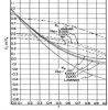
The pressure drop through a constriction can be estimated by

dP= 1/2*k*density*velocity^2

Where k is a pressure loss coeficient.

This returns the presure in pascals when using si units /100000 to convert to bar.

With the velocity know you can calculate the required port area/clearances.

The difficulty in this approach is finding a value for k as this will be a function of piston position.

I'll have a dig around to see if I can find an approximation to give a ball park figure.

Sam
 
Another thing to bare in mind is the limit of hydralic damping. In an enclosed system with no ports for water to escape the piston will only ever be slowed to 11.36m/s. This is based on an 8mm free shaft travelling at 30m/s and a 13mm piston.

If you consider a stock shaft with 9mm but end the resultant piston speed goes up. I.e you will alway need additional mechanical damping.

Sam
 
Last edited:
It would be clearer if you draw a configuration you are talking about. The situation is different for shaft with line slide from that for free shaft. I think you should take the kinetic energy of the piston, not only the pressure in a gun.
 
I believe the most significant losses will be a contraction loss Kc and an expansion loss Ke. These vary according to the area ratio. In our case (damper passage way cross sectional area/(piston cross sectional area - shaft cross sectional area).

This relationship is shown attached.

I estimate the minimal area ratio to slow the piston is around 3:1 (0.33 on the x axis), giving both Ke and Kc ~0.45 total K of 0.9. This leads to a pressure of 36.45 bar (which is slightly below the minimal value calculated before).

Anything less is likely to result in only slowing the rate of acceleration of the piston/spear. The same end velocity could be archived using a marginally lower gun pressure.

I think the above reasoning holds however if you see a mistakes or practical experiments show differently please let me know.

I hope this provides some help. If any further info is needed let me know.

Sam
 

Attachments

  • image.jpg
    image.jpg
    37.1 KB · Views: 235
Thanks to your help and suggestions!
I used different approach, but only the result is important. If you look at the last pictures you can see that I have same cross section all the time during braking the piston (braking distance is about 10 mm).
 
Hi Tromic

I'm still can't get to a pc so will try to explain one of my points again.

Here I'm comparing relitive areas so will leave out the pi/4x10^6 term when calculating areas as they will cancel out in the end.

A spear 8mm dia at 30 m/s will leave a void behind it of

8^2*30*dt

Where dt is the change in time considered.

If the piston moves forward to fill this void it displaces a volume of

11^2*v*dt

Setting these two volumes equip to each other with no water being forced out of the ports gives

V~16 m/s

This is the slowest piston speed you could achieve with this set up. In reality water will be forces out of the ports leading to a higher piston speed. As you have no mechanical damper in your design I suspect an instuntanious reduction in speed from a minimum of 16m/s to 0m/s will break your piston.

Sam
 
I've just done some hand calcs to estimate the effects of water discharging through the ports. This neglected the rubber tubing over the ports and resulted in a piston speed of around 20m/s.

I'll try to explane the calcs I've done step by step.

The first step is to calculate the area ratio between the flow area/piston area.

In your case

(11^2-10.7^2)/10.7^2 = 0.057 (this is the value to lookup on the x axis of the graph posted).

Following this value up gives a Ke value of 0.5 and a Kc of 0.9. Total k = 1.4.

Using P=0.5*k*density*v^2 and setting the pressure equip to the gun pressure 20 bar (2000000pa) gives a velocity through the anular gap as 53.45 m/s.

Multiply this speed by the area 11^2-10.7^2 gives a volumetric flow out of the system.

Add this volume to void created behind the spear. Gives you the total flow out of the system. Devide this by the area of the piston gives you the speed of the piston.

(11^2-10.7^2)*53.45 = 348
8^2*30 = 1920

348+1920 = 2268

2268/10.7^2 = 19.8m/s

A bit long winded but I'm 95% sure this method holds.

Hope this helps/saves a piston being sacrificed.

Sam
 
This was my last configuration that I tested for 11 mm barrel, TombaF700HN.
It had both hydro damper and normal, rubber, dumper:

http://forums.deeperblue.com/pneuma...mba-all-one-barrel-sealing-48.html#post903966
http://forums.deeperblue.com/pneuma...mba-all-one-barrel-sealing-48.html#post903872
[ame]http://youtu.be/1v9afW746gk[/ame]


Before using it with hydro + normal damper I tried it with hydro damper only. It worked good too, on 20 bar in air.

http://forums.deeperblue.com/pneuma...mba-all-one-barrel-sealing-46.html#post902711

http://youtu.be/cq27eMYlVa0

There is one fact more to have on mind. During braking the piston the average speed of the shaft is about 2.3 X the average speed of the piston. This is important because the shaft tail creates empty place behind it when separating from the piston. That empty space could be filled with water left in muzzle after hydro braking.
 
Last edited:
I've just done some hand calcs to estimate the effects of water discharging through the ports. This neglected the rubber tubing over the ports and resulted in a piston speed of around 20m/s.

I'll try to explane the calcs I've done step by step.

The first step is to calculate the area ratio between the flow area/piston area.

In your case

(11^2-10.7^2)/10.7^2 = 0.057 (this is the value to lookup on the x axis of the graph posted).

Following this value up gives a Ke value of 0.5 and a Kc of 0.9. Total k = 1.4.

Using P=0.5*k*density*v^2 and setting the pressure equip to the gun pressure 20 bar (2000000pa) gives a velocity through the anular gap as 53.45 m/s.

Multiply this speed by the area 11^2-10.7^2 gives a volumetric flow out of the system.

Add this volume to void created behind the spear. Gives you the total flow out of the system. Devide this by the area of the piston gives you the speed of the piston.

(11^2-10.7^2)*53.45 = 348
8^2*30 = 1920

348+1920 = 2268

2268/10.7^2 = 19.8m/s

A bit long winded but I'm 95% sure this method holds.

Hope this helps/saves a piston being sacrificed.

Sam

I suppose you were talking about this drawing, although you had been mentioning piston 13 mm, on beginning?

http://forums.deeperblue.com/pneumatic-spearguns/95313-shock-absorber-3.html#post901302

Actually, your and mine approach are basically very similar.
 
Last edited:
Hi,

I've been considering a 13mm barrel as that's what I'm planning on modifying. I was going to keep it wet barrel for simplicity. However I have always been interested in how a 11mm barrel would perform with an 8mm shaft. Have you used this setup yet or is it for a future project?

Out of interest was the 2.3x speed multiplayer for an older design? For you current disign would it not be 10.7^2/8^2 ~ 1.79 or am I missing something?

With the dampers you have made so far has there been a noticeable reduction in sound as it's hard to tell from the videos?

Unfortunately I haven't got access to a lathe etc so can't do practical tests that easy. Hence all the theory. It's always nice to get to the same/similar result two seperates ways to give you confidence in it.

Sam

In my current project I had:

11.1 mm damper body ID, 10 mm braking distance (could be adjusted by amount of injected water);
7 mm shaft;
boring in piston 7.05 (actually in additional part in front of the piston)
piston OD 10.8 mm.

I have not made hydro damper for 8 mm shaft with 11 mm barrel yet, it was just an option, and I was interested in testing the hydro damper only.

I got "2.3 x" as 30/avarage_speed during braking, assuming that deceleration force is constant, from
v_i = 30 - sqrt(2*deceleration*braking_distance_i),
for i from 0 to 10 mm, in small steps, and v_0 = 30 m/s, and calculating mean value from that (excel).

About sound reduction with hydro damper, I do not know yet. I should test it in water.
 
Last edited:
In my current project I had:

11.1 mm damper body ID, 10 mm braking distance (could be adjusted by amount of injected water);
7 mm shaft;
boring in piston 7.05 (actually in additional part in front of the piston)
piston OD 10.8 mm.

I have not made hydro damper for 8 mm shaft with 11 mm barrel yet, it was just an option, and I was interested in testing the hydro damper only.

I got "2.3 x" as 30/avarage_speed during braking, assuming that deceleration force is constant, from
v_i = 30 - sqrt(2*deceleration*braking_distance_i),
for i from 0 to 10 mm, in small steps, and v_0 = 30 m/s, and calculating mean value from that (excel).

About sound reduction with hydro damper, I do not know yet. I should test it in water.

Regarding 2.3 x lower (than 30 m/s) avarage speed during braking, the more precise value is close to 3 x. Ive just did calculation using integral function and wolfram alpha. But this is theory only. Real verification would be testing actual piston life through usage in gun. I suppose it would last longer than with normal, rubber, shock absorber.
 
Last edited:
In my current project I had:

11.1 mm damper body ID, 10 mm braking distance (could be adjusted by amount of injected water);
7 mm shaft;
boring in piston 7.05 (actually in additional part in front of the piston)
piston OD 10.8 mm.

I have not made hydro damper for 8 mm shaft with 11 mm barrel yet, it was just an option, and I was interested in testing the hydro damper only.

I got "2.3 x" as 30/avarage_speed during braking, assuming that deceleration force is constant, from
v_i = 30 - sqrt(2*deceleration*braking_distance_i),
for i from 0 to 10 mm, in small steps, and v_0 = 30 m/s, and calculating mean value from that (excel).

About sound reduction with hydro damper, I do not know yet. I should test it in water.

One way you can check the sound from a pneumatic gun is to shoot downwards over a flat sandy bottom from the surface, the bottom being some distance below. The sound of the gun reflects back from the bottom. I have noticed that my pneumatic gun seems louder when used in such situations.
 
I might test it in a lake or river but I will wait to test it in sea. I am more interested in efficiency of hydro damper. That would not be easy to test.
 
Last edited:
For another forum I measured the shock absorber rubber sleeve in my "Cyrano" (purchased in 2000) to see how much the rubber sleeve could compress and fill up the open space in the muzzle surrounding it. The gap around the rubber sleeve is quite small and if the rubber itself cannot crush then the "telescoping movement" of the rubber sleeve is about 2 mm, some of which is already used up as the muzzle nut is tightened and slightly compresses the rubber sleeve to stop the shock absorber rattling in the muzzle and of course providing a return action on the shock absorber anvil when the gun is cocked and ready to shoot.
muzzle shock absorber action 2.gif
 
Last edited:
To have 4 mm of travel on the shock absorber anvil the rubber sleeve has to either compress itself or extrude somewhere else into an available gap. I think the latter is unlikely, but another possibility is the base or reference position line is moving. Recently I unscrewed the muzzle nut on my "Titan" as I wanted to check the rubber sleeve measurements of a metal piston and a metal shock absorber gun. Usually these nuts are not removed as their screw thread tends to seize up and only a small ribbed rim protrudes which is all that you can grab with some multi-grip pliers as there is no hex nut on the nose of the earlier guns. The "Titan" has a slightly longer muzzle nut than a "Sten" and it extends further out from the muzzle body, but the reason I chose it is that this nut has always tended to undo after a large number of shots and I just screwed it back in whenever I saw that it had moved. So it was easy to remove once I depressurized the gun. However like you I put the muzzle in a bench vise (but with the front muzzle nut removed) and tried to push the shock absorber body out using an old "Sten" piston as the pushing element. To protect the muzzle and piston tail from the grooved faces on the bench vise jaws I used a flat steel plate at the rear end and a flat piece of wood at the front end. I then wound the handle on the vise and thought that the shock absorber must be moving, but then realized the muzzle nose was just pushing into the wood. To avoid bending the piston tail I stopped winding the vise handle and backed the jaws off to remove the muzzle from the vise. To my surprise the shock absorber body and sleeve assembly never budged at all and was stuck firmly in the muzzle and looking in it seemed that there were no gaps visible around the rubber sleeve. Those gaps were probably there originally, but over 30 years of sustained gun internal pressure the rubber must have taken a "permanent set" in the compressed position, in other words it has molded into a new shape. Hence to remove the rubber sleeve I would probably have to destroy it and that is not going to happen. Here are some photos that I took, you can see my special muzzle removing wrench with the two bolt "handles" that terminate in pins that fit into the small muzzle relief ports on older guns.
Titan muzzle removed 1.jpg
Titan muzzle removed 2.jpg
 
Mares changed from metal pistons and shock absorbers to plastic versions many years (decades) ago. The stated purpose behind the change was to eliminate corrosion in the inner barrel in the non-swept area just in front of the forward piston seal which is where water always sits after the gun is discharged and even after the gun is washed. Eventually this semi-trapped water dries out, but galvanic action can occur between the steel piston and the alloy inner barrel over time. So the shock absorber has been originally designed to work with heavy pistons plus the restriction imposed by pumping water out of the inner barrel during the shot. At some later time Mares took advantage of the plastic piston's lower mass to open up the muzzle relief ports as they could then afford to use less water pumping action to control the piston impact than they had used previously. This could be why Mares have stuck with wet barrel guns as the plastic version of their shock absorber may otherwise eventually crack, it being a design that dates back to their original guns.
 
Last edited:
On the right is Mares mirage shock absorber body. I suppose the lower OD section is for "extrude somewhere else" into an available gap.
2ln8k0o.jpg
 
DeeperBlue.com - The Worlds Largest Community Dedicated To Freediving, Scuba Diving and Spearfishing

ABOUT US

ISSN 1469-865X | Copyright © 1996 - 2024 deeperblue.net limited.

DeeperBlue.com is the World's Largest Community dedicated to Freediving, Scuba Diving, Ocean Advocacy and Diving Travel.

We've been dedicated to bringing you the freshest news, features and discussions from around the underwater world since 1996.

ADVERT