• Welcome to the DeeperBlue.com Forums, the largest online community dedicated to Freediving, Scuba Diving and Spearfishing. To gain full access to the DeeperBlue.com Forums you must register for a free account. As a registered member you will be able to:

    • Join over 44,280+ fellow diving enthusiasts from around the world on this forum
    • Participate in and browse from over 516,210+ posts.
    • Communicate privately with other divers from around the world.
    • Post your own photos or view from 7,441+ user submitted images.
    • All this and much more...

    You can gain access to all this absolutely free when you register for an account, so sign up today!

Hawiian trigger design

Thread Status: Hello , There was no answer in this thread for more than 60 days.
It can take a long time to get an up-to-date response or contact with relevant users.

oneoldude

New Member
Feb 7, 2005
50
4
0
Any spearo historians out there?

I understand years ago Hawiian spearos developed a home brew trigger mechanism that used a ball bearing as the sear. I have been unable to find any information on the design.

Anyone seen or used the design and wish to describe it or show pics or drawings of it? How about describe its good and bad points?

From what I can gather it could be durable, strong, safe and very smooth. What more could one ask? And if it is easy to make it could be the heart of a great project.

PM me if you like.

Thanks

oneoldude
 
Hi Spearos,

Many years ago when I just got back from Dental school, I hooked up with some local divers who in my opinion where pioneers at that time. I was the youngest of the group by twelve years. They always used to say they were older than dirt. The great thing is that even now some of them are still diving and still dive as deep as they ever did. Wet suit? That was for sissies!
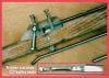
Back then your production guns were Arballetes as we called them then and we used either those or Hawaiian slings. One gentleman who worked in the Pearl Harbor shipyard looked at how the sear and triggers worked in the arballetes and decided to make his own trigger. To decrease the friction on the shaft. he used a ball bearing. Because the contact point was so small on the bottom of the shaft and that the shape was round like the euro type sears, this trigger was extremely smooth. And this was a one piece trigger. To hold the trigger forward, divers using this type of trigger, literally used rubber bands or thin pieces of surgical tubing.
But they have a saying called "reinventing the wheel". Basically this mechanism was a copy of a trigger mechanism like the ones in euro guns but with a sear /trigger in one piece. It still had the limitations of the euro guns.
I remember later when I got my new JBL and asked "Yama" why he didn't put stronger bands on his gun. Instead he had guns of different lengths depending on how far he needed to shoot. His answer was that if you make the band pull too strong, it gets harder to pull the trigger, and also the gun could fire on its own. This is the same thing that limits euro guns from having three bands or too much pressure on the trigger. Needless to say, I rarely dove in front of him.
Euro triggers with its half round sear is very smooth because the half round shape allows for a very even release when the trigger is pulled. The shaft is held in place not because the round sear is holding it, but because the shaft is pinched between the top of the housing and the sear.
American mechanisms are stronger because the sear is at a 90 degree to the bottom of the shaft and it is mechanically holding the shaft in place.
So to get back to this ball bearing mechanism. Is it still use today? Yes, there are a few old timers using them still. Why? Because they could be made at the ship yard for free and it was inexpensive. Back then there were no pre-made enclosed trigger mechanisms like Riffe, Alexander, or Aimrite. Most of the divers today have switched to either euro guns or American type mechanisms.
Another type of way to make a smoother trigger was to have a square notch cut into the rear of the shaft that the trigger goes up into to hold the shaft. And on this sear that went into the notch the shipyard workers would weld a small roller bearing. This made for and even soother trigger. But again the limitations were the harder the band pull the harder to pull the trigger. Friction was the limiting factor. Unless you have a two piece or even a three piece mechanism, you will be limited in the amt of bands or pressure you can put on the sear holding the shaft. The biggest problem was that you had to custom fabricate every spear.
This is just my experience in seeing how divers with the resources and ingenuity in Hawaii did to make a better speargun at a fraction of what store bought arbelletes cost. Its rare to see any spearos with this type of gun now. If you do see any, they are older than dirt.:))))).


Aloha, Daryl
 
Hi Dayrl,

Thanks for the response. I guess that the reason I have an interest in those triggers is because I was around when dirt was invented and for now, I am interested in a gun with only two bands.

I did not know those designs were one piece trigger/sear designs. That certainly puts a damper on the design. I was hoping they were a bit more sophisticated.

I did a search on the US Patent web site and found an interesting design. I do not know if it was ever produced, but it should be out of patent protection by now. I have attached a picture of it (I removed the safety and number lines for clarity) and included the patent number for anyone interested in reading the patent.

After reviewing that design I do not see how it could possibly be weaker than American hook type triggers unless the frame is made of cheezy material and fails. After all, you would have to deform the shaft to get it out of its hole without pulling the trigger.

Since that design requires significant machining, I came up with a simpler design. It is a takeoff of the design of a trigger that Chris (deftothecrown) described to me. I believe his gun is called a Sea Hunter. Supposedly they are very smooth in pull and release.

I have attached a not-to-scale concept drawing of what I cooked up. I left out springs and safety for purposes of clarity. I have not tried it yet because I have not found appropriate stock for the frame.

In any event, thanks for the reply. It is interesting history.

Anyone else out there with home brew trigger designs of any type, please share.

Thanks again,

oneoldude
 

Attachments

  • Trigger Ball.jpg
    Trigger Ball.jpg
    59.2 KB · Views: 363
  • Trigger.JPG
    Trigger.JPG
    52.2 KB · Views: 353
Last edited:
oneoldude said:
Anyone else out there with home brew trigger designs of any type, please share.

Thanks again,

oneoldude

What an interesting thread! I had a hunch that ball drop trigger concept had been done before. I'll have to add that history to my home built speargun web page.

I've built two guns with homemade triggers with the same drop seer style trigger mechanism. My triggers use a round pin for the seer instead of the ball and a simple lever for the trigger.
Click the thumbnail for a larger picture:
I have a web page that describes these guns and their home built triggers in more detail. Trigger pull can be fine tuned to your liking with this design.
Here's a link to that page: http://flshoredives.nexuswebs.net/biggun.html

And another type of simple trigger: http://flshoredives.nexuswebs.net/speargun.html

:)
 

Attachments

  • guntrig.jpg
    guntrig.jpg
    72.3 KB · Views: 381
Last edited:
Hi Fish Tail,

Hello from a native Floridian. I have seen your site. It has been an inspiration to me. Your first design is similar to the design of my first home brew speargun almost 50 years ago. It worked pretty darn well until I tried to bag a very large snook. The shaft bounced off of its gill plates so I was forced to go to store-bought.

After browsing your site, and marvelling at your cleverness, I started thinking about using a ball rather than a cylinder as you have. Also I did not like the fact that with your design you must re-tune the trigger for different band strengths. So I noodled DB and found defothecrown who has a commercial gun, Sea Hunter I think, that has a ball type trigger. He sent me a drawing of the thing. The drawing is attached.

From my emails with def I can describe how it works. When the trigger is pulled the block slides forward and the ball falls behind the block freeing the shaft. Immediately thereafter the red spring pops the ball back up. Then as the trigger returns, the block regains its original position.

It would appear that you would have to pull the trigger to re-load the spear. Not so! When you insert the spear, the ball is pushed backward. Then it is pushed down behind the actuator block. When the notch in the spear is in the right place, the red spring pops the ball back on to the block and into the notch and it is ready to fire again. It is nice not to have to pull the trigger to insert the spear. I might add that def tells me the block is not angled in any direction. In other words all angles on the block are 90 deg.

In your initial message you said to me, "The design in the color graphic in the post above won't work unless the triggers indent is to the left of the ball so when you pull the trigger back the slot in the shaft slides backward to meet the ball. I tried that concept prior to making my first butter knife (lever) trigger. When you load even one band the trigger pull gets so stiff the shaft won't release without a huge effort on the trigger. The reason was as stated above-> No mechanical advantage of a lever to overcome friction between the parts."

Take what I say here with a pound of salt. I am not an engineer. But, I suspect there is a form of mechanical advantage in the ball type designs. When the spear notch is pushing the ball forward there is a force vector forward and a force vector down. If the force vector forward is large by virtue of the angles of attack created by the rear notch angle acting on the ball, I suspect the force vector down is small. Therefore the downward pressure may be very much less than it might at first appear. If this was not so, then the patented design and the commercial design could not work. I suspect the devil is in the details and in understanding the vectors at work because if the downward vector is large and the forward vector is small we could have friction problems.

Also, if you look at my color drawing, note that the pivot for the trigger is below the actuating rod. The top of the trigger therefore will move forward pushing on a pin in the actuating rod. that will move the rod to the left for the ball to fall into the actuating rod detent. There is mechanical advantage in this design. The mechanical advantage can be varied by changing the ratio of the distance between the two pins and the length of the trigger. Whether that will be enough of a mechanical advantage for a practical trigger remains to be seen.

By the way, would you be so kind as to post a copy of the design that did not work? That would be very interesting. As the saying goes, we learn more from failures than from successes.

This has been great fun so far. I hope others will join in with their experiences, good and bad, with all sort of home brew triggers.

Thanks,

oneoldude.
 

Attachments

  • Trigger_3.jpg
    Trigger_3.jpg
    13.2 KB · Views: 488
Last edited:
Looks like a solid design to me. I'd love to see a diagram w/ the springs, safety, line release etc if you have time. I know you said your diagram isn't to scale, but it appears you are using an actuator and spear that are of similar diameters. I recall a line in Terry Maas' Blue Water Hunter that says to limit a pushrod to 1/8" D so the weight of the pushrod won't fire the gun accidently. Just something to keep in mind as it wouldn't be too much work to tap the actuator and insert a threaded rod to err on the side of safety.

Secondly, you seem really fond of a ball design over a cylinder. I'm not sure if this would make the release any smoother. I suppose w/ a sphere you'd have a single point of contact theoretically, while with the cylinder you'd have a single line. I guess the less contact the better so.... It would be neat to try both. I know your only going for a couple of bands so say ~180lbs on a single point. Is that enough to deform the ball or spear or actuator, probably not?

Are you planing on having a actuator-independant reloading cycle? It seems you have a solid housing in your diagram that would prevent this from being possible.

I've really been learning alot about different trigger designs since you started researching your project. I don't know if you subscribe to freedive list, but there was recently a slew of postings about different designs. It's nice to see that people are stepping outside the realms of convention. Keep us posted.
 
Hi Oneoldude!

I'm really enjoying this sharing of knowledge!

I remember reading the post about the "sliding block" type drop seer. That design also needed levers to work. That's a neat design!

When I first replied to your design I didn't recognize that the trigger was separate from the actuator and was actually a lever that would provide the mechanical advantage needed to overcome the friction between the spear, seer, and actuator while under load. That's why I later changed my post about your design. If you have enough leverage you will be able to overcome the friction between the parts of your design. It should work fine if you can get enough travel in the actuator! Your design concept is correct. My bad- sorry.

The failed version I tried had no lever as part of the mechanism and it locked up solid. I've whipped up a quick drawing of the failed design.
(Click for larger view)

Your understanding of the sloped shape of the shaft detent helping push the seer down is accurate. The forward forces on the seer in my design and yours above are transformed into a rolling motion because the ball/ cylinder can't move forward due to the seer being trapped by the housing. It works well!

In tuning the triggers I made, I discovered that when you tune for two bands of the same strength the trigger pull for just one band is actually only slightly lighter to the touch. I tuned for a firm trigger. The result repeated itself when I made the second trigger. It doesn't significantly change the way the trigger pulls- one band or two. With the second trigger I built; the trigger was slightly longer because of a thicker gun barrel. When I tuned the shape of that trigger I found all that was necessary was to make certain the seer never had to roll up hill as the trigger was pulled. The top of the trigger really has no "slope" to it until the seer gets near the edge of the trigger where I've created a slight downward slope on the trigger face. At that point the seer begins to move away from the shaft. In both triggers the pull (feel) is very stable and doesn't ever change in use as long as the parts don't wear or deform. Your design will likely have the same stable qualities.

If I'm thinking correctly your trigger design should have the same forces to overcome as mine. As long as the seer doesn't have to roll "up hill" as the trigger is pulled and you have appropriate leverage to overcome friction between the parts I think your trigger design will be a success!

My guns are powered to propel a known shaft weight range so I have to keep my band power within the range needed to get the results I'm looking for from the shafts I use. I'm finding that one 5/8 inch band easily gets it done in most cases for me but the guns could use two bands if needed. I like to use 5/16 inch cutting tips with my 5/16 inch shafts. Those small and sharp cutting tips don't seem to need the power I've built into my guns. The shaft speed is nice though.

I hope that helps your understanding of my trigger building experiences.
:)
 
Last edited:
  • Like
Reactions: Alison
Def,

It seems you have more confidence in my design than I do. Hopefully, time will tell.

There are several reasons I favor the ball over the cylinder. The first is that the machining of the frame can be done with only a drill press and drill bits. I do not have access to a mill. The second is that when using a cylinder you must be very concerned with it getting crooked and hanging up. A perfectly symetrical ball has less of a problem with that. Also, if the ball is larger than the hole for the spear, it cannot fall out of the frame. That allows you to avoid the through bolt design that Fish uses and you can make a narrower less obtrusive housing that can be inletted into the stock better. Another is that SS bearings are much harder than common SS bolts. Otherwise I like the fact that the cylinder design has more bearing surface for the spear notch to ride on. As for wear, check your Sea Hunter and tell us about its wear patterns.

Thanks for the tip on rod wt. I will keep it in mind.

Yes I have cooked up a trigger independent cocking mechanism. But it would require milling and a couple more parts. Not worth it at this stage of the game.

As you can see from my clumsy drawing, I am only a beginner with Auto-CAD. It took me a very long time to draw what I did. As I get a bit better with it I will try to come up with a more complete drawing.

I went to the freedive list and could only find posts about man-eating trigger fish. Got a URL for those trigger mechanism articles?

Thanks

oneoldude
 
  • Like
Reactions: Alison
I love this stuff :D Its about as good as any hobby get as far as Im concerned, I wish I could do it myself :(
Keep it comming
 
HI Fish,

I supposed you did figure out my poor drawing but I wanted to address the mechanical advantage issue anyway for purposes of clarity.

Thanks for posting the failed design. I now understand why it was problematic.

It is good to know that once your trigger is "tuned" it does not need any more fiddling. That makes me feel much better, especially in regard to safety.

I have had a mini-epiphany in thinking about your trigger. If you read the Patent I addressed above, the discription points out the importance of making sure the profile of the trigger where the bearing rests is a perfect circle with radius at the center of the trigger pin until the drop point is reached. The reason is obvious. If there is a hair of free play in the spear shaft hole and the radius is sized right then there could never be a lock up of the trigger (trigger to sear to shaft to housing vertically) and a very, very smooth trigger pull should result. This feature could be easily implimented in your design with the trigger pinned through your housing. It would be strong as hell so long as your plastic housing or the pivot pin do not fail. Also, your actuating rod would not have to be bent backwards at the rear and if you used a bearing (larger than the hole for the spear shaft so it cannot fall out) you would have a neat and tidy mechanism. You could even fit a spring to return the trigger and the ball would slide up automatically. See the patent.

I suppose you are using polycarbonate (lexan) for your housing. Are you? I have had no experience with it so drilling and cutting it are a bit scary to me. Suggestions? I have been looking for a sufficiently thick bronze plate for my design with no success. Any suggestions on sources for the proper plastic?

And yes this has been fun.

Thanks

oneoldude
 
Fish,

One more thing. It might be that using a ball with the plastic you are using results in a local compression of the plastic that results in a dimple or detent that tends to fix the ball. In essence it could lock up the ball. If that happens with a ball, your through bolt design might work better because it spreads out the pressure over a greater surface area and the dimpling might not happen. Perhaps a harder material might be better for a ball design.

Just a thought.

And if you do try it in plastic, please let us know what happens.

Thanks

oneoldude.
 
Hi Alison,

You can do it.

If you can freedive, spearfish and fillet your catch, you can apply the same level of concentration and concern for safety to working with motorized tools. Just watch your fingers!

Start out with something simple like a Hawiian sling. I am sure you have a friend or two with wood working tools who will show you what to do, allow you to do it and watch you to be sure you don't hurt yourself until you are accomplished. You can be as fancy as you like with a sling, all the way to a glass-like finish. And everything you learn will be a stepping stone to more complex projects in the future.

Just keep in mind that if you screw up, you can toss it out and for a few pence start over again. We have all done it many times ourselves.

Yes, you can do it.

oneoldude
 
oneoldude said:
I am sure you have a friend or two with wood working tools
Ive got a husband who is a cabinet maker and a brother who was an engineer, so I wouldnt be allowed to ;) Still I make the tea :eek:
I just love this back to basics aproach, I have so much admiration for this sort of thing, still I made my own flashers :D
 
Lexan cracks pretty easily. They make special 'plastic' drill bits w/ very sharply angled points. Even pre-drilling pilot holes won't stop all the chipping w/ normal bits unless your drilling small holes w/ sharp bits. It also melts at low temperatures so go slowly and never drill/cut more than a couple of inches without taking the tool out to allow the lexan to cool.

Have you considered aluminum 6061 t1? It would be very easy to machine and then you could heat treat it and artifically age it until it was very hard. You could also home-anodize the piece. I always joke around that aluminum is a plastic, but its a damn strong plastic at that.
 
Def,

My experience with plastic is very bad. Cracks, chips etc. all over the place.

I am considering Al. It is easy to anodize and color. You can cut it with a chop saw and a drill press works beautifully on it. But I know nothing about tempering or heat treating it or artificially ageing it.

I am concerned about its life in salt water (even if anodized) and have considered a zinc anode as part of the ballast to help prevent corrosion.

Want to tell us about hardening and ageing 6061? I did not know you could do that to 6061.

Ain't it a shame SS is so hard to work?

Thanks

oneoldude
 
oneoldude said:
HI Fish,

I have had a mini-epiphany in thinking about your trigger. the discription points out the importance of making sure the profile of the trigger where the bearing rests is a perfect circle with radius at the center of the trigger pin until the drop point is reached. The reason is obvious. If there is a hair of free play in the spear shaft hole and the radius is sized right then there could never be a lock up of the trigger (trigger to sear to shaft to housing vertically) and a very, very smooth trigger pull should result.

That geometric relationship and the resulting dependability is the objective.

Mechanisms that are too precise bind up when crud gets into the mechanism. My machining and work holding methods were pretty crude so tight fits were not a problem. ;)

I ground my triggger face profile flat at first using a bench grinder. I then adjusted it to a very minute arc so that my seer would never be pushed back up into the spear as the trigger was pulled to the firing position. I polished the trigger face smooth with some fine grit sandpaper. The spear is being pulled out of the trigger mechanism by the force of the bands. The shape of the seer detent in the spear acts like a wedge forcing the seer down against the face of the trigger. In order to push the seer up you would have to move the spear (wedge) backwards in the mechanism to create room to move the seer up. With my band selection there's 100 to 200 pounds of force driving that "wedge" forward into the seer. It would take that much force to move it back. That's why its so important to have the geometry of the trigger face close to correct. In practice I found that the tolerances are pretty wide as long as the seer doesn't have to slide or roll uphill as the trigger moves out from underneath the seer. The trigger on my 38 inch gun stiffens just a tiny bit right before it releases the seer. That's because I have a slight geometry defect in my trigger face that forces the seer upwards at that point. I kind of like that because it lets me know that the trigger is on the edge of firing. Slight defects in trigger face geometry are easily overcome by the leverage created by the length of the trigger arm. The more downward the slope of the trigger face, the easier the trigger pull becomes because the band force starts to assist in pulling the trigger. That also means that too much "slope" is bad because the trigger could discharge on its own. My guns triggers are tuned to avoid that condition but still fire well.

Another question asked was what material the plastic trigger housing was made from. I cut my housings from a chunk of acrylic I found at a garage sale a while ago. I used a table saw with a carbide tipped blade to cut it to shape and make the slots in the plastic housing. A drill press was used to drill the holes for mounting it. I used to work for a company that used acrylic in some structural applications and have learned to machine it without compromising it's integrity. Stainless steel would have been the ultimate material but I can't cut stainless with my table saw. rofl


My objective in designing this trigger was to create a safe, strong, simple, and dependable trigger that could be easily maintained and repaired with parts that are easy to get or fabricate with common tools. The seer's stainless steel bolt and cap nut are easily aquired just about anywhere in the world. Most places in the world have stainless steel kitchen flatware for trigger stock and bolts for pins. The trigger housing could be assembled from pieces or cut from a solid piece of material. I can rebuild the entire speargun without depending on a parts supply that may ultimately go out of production or be difficult to aquire. I decided that the closer I got to my objective the closer I would be to having a tool that'll always be ready to do its job.

Designing a production level, self contained trigger mechanism has already been done very well by others. Not really any need for me to pursue that objective.

:)
 
Last edited:
I can see the 'Far Side' cartoon now. The grizzeld shipwrecked guy with the tattered shorts and long beard sitting on the tiny island w/ a single palm tree. Then a crate washes up that simply marked 'Steak knives'...damn serrations.
 
I could probably get pretty far with a crate full of steak knives! It would give me something to do.

rofl
 
oneoldude said:
A commercial gun, Sea Hunter, that has a ball type trigger. The drawing is attached.

From my emails with def I can describe how it works. When the trigger is pulled the block slides forward and the ball falls behind the block freeing the shaft. Immediately thereafter the red spring pops the ball back up. Then as the trigger returns, the block regains its original position.

It would appear that you would have to pull the trigger to re-load the spear. Not so! When you insert the spear, the ball is pushed backward. Then it is pushed down behind the actuator block. When the notch in the spear is in the right place, the red spring pops the ball back on to the block and into the notch and it is ready to fire again. It is nice not to have to pull the trigger to insert the spear. I might add that def tells me the block is not angled in any direction. In other words all angles on the block are 90 deg.

When I first looked at the drawing of the Sea Hunter mechanism and tried to visualize it working per the explanation above I just couldn't get the ball back into loaded position with the trigger block already in the ready to fire position. If the drawing is correct the space between the spear and the block seems too small to allow the ball to pass from behind the block back into the notch in the spear with the trigger block already back in the ready to fire position. The space would have to be too small to allow the ball to pass to keep the spear from discharging as soon as a band was loaded. Hmmmmm.

Link to drawing:
attachment.php


Am I missing something?
I've never seen one up close but it looks like the ball may be permanently attached to the spring in the position shown in the drawing. When the trigger is pulled the block would move out from under the ball and spring and the ball/spring would drop allowing the spear to leave the mechanism. The ball and spring should pop back up after the spear has left the mechanism. The reloading process would start by pulling the trigger then inserting the spear which would push the ball and spring back down and behind the trigger block to allow the spear to enter the mechanism. The ball and spring would pop back up and into the spear notch at which point the trigger could be released moving the trigger block back into ready to fire position.

If that's the way that works It looks like very clever way to control the seer without a complex trigger housing for support! I wonder how many cycles the spring is good for?
 
Last edited:
Yes. I drew this quick and dirty on a painting program. The drak gray 'L' shaped block is not solid in the first photo. I didn't want to blow this up to three plus layers. The 'L' block is not solid but supports the back of the 'actuator'. The cylinder can go to the left of this block in the first drawing. Please keep in mind there is some internal plastic housing molding that was 'sacrificed' for clarrity and to expidited the drawing process. Sorry for the confusion.

I'd take photo's but there isn't enough contrast and I think it would be more confusing than the diagram.
 
DeeperBlue.com - The Worlds Largest Community Dedicated To Freediving, Scuba Diving and Spearfishing

ABOUT US

ISSN 1469-865X | Copyright © 1996 - 2024 deeperblue.net limited.

DeeperBlue.com is the World's Largest Community dedicated to Freediving, Scuba Diving, Ocean Advocacy and Diving Travel.

We've been dedicated to bringing you the freshest news, features and discussions from around the underwater world since 1996.

ADVERT