New Bulkhead In The Making - Part 5 - How Does The Valve Work?
I haven't seen a valve like this before - maybe it's out there as airguns have been around for ~70 years by now - but I hope it will work as I intend it to. That said, maybe I got something wrong, haha.
View attachment 60878
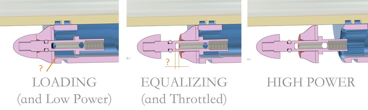
Let me try to explain how I hope it will work...
In Pos 1 for Loading I initially had a compression spring between the front "cap head" and the valve cap to force the valve cap closed against the lip. The plan was for the selector knob to be locked into the rearmost gate and then the spring would push the valve cap shut. But now I think it may not be needed, because I can use the pressure to my advantage here.
If the PR rod is 4mm in diameter, then at 30bar I'll have ~4kgf pushing the rod rearwards "out of the handle". So, instead of locking the knob into a gate, I will keep it in an open axial slot with extra space - so, it's kinda floating and can move rearwards as much as it wants until the valve head pulls the valve cap against the lip - which then seals it. Now, there will be 4kgf on that seal.
So, far the surface area of the valve cap itself doesn't matter - only the area of the rod. But as soon as I start pumping and building a pressure differential between the front side of the valve cap and the rear side, the cap's area now governs how much force is keeping the cap sealed against the lip. With one pump, the pressure differential will go from 0 to maybe around 7bar which results in a force on the cap of ~5kgf (I guess plus whatever pressure is now acting on the rod). After three pumps, the force could be 15kgf and after 5 pumps it's close to 20kgf (not 100% on the numbers, but they should be in the ball park).
This is how I am hoping the loading part will work - that even before pumping, the pressure in the gun will keep the valve shut tight. And as soon as I start pumping, the valve will be pushed even harder against the lip.
And then after loading, we push the knob forward to the Equalizing position and the air will run from the forward chamber through the internal bore in the rod to the rear chamber until there is no pressure differential. How long this will take, I don't know. Maybe I need a gate to hold the knob in this position or maybe I can just hold it open against the pressure of the gun. With e.g. 35bar forward chamber in the the force to open a 4mm rod would be 4.5kgf. Whereas if I go to a 3.5mm rod, it would drop to 3.4kgf.
Also, in theory this position could be used for a throttled shot but I think the Low Power shot is a better option.
Once the pressure has equalized, the main valve will open with just the force acting on the rod. So, it would need a gate to hold it in the open, Full Power position.
The main advantage to this valve - if it works - is that the forceful slamming when opening the valve after pumping would be eliminated. And another real world benefit is that going from High Power to Low Power would be very easy as you just need to flick the power regulator out of the High Power gate and the valve will close automatically and fairly gently.
Let me know if I got all this wrong
")