
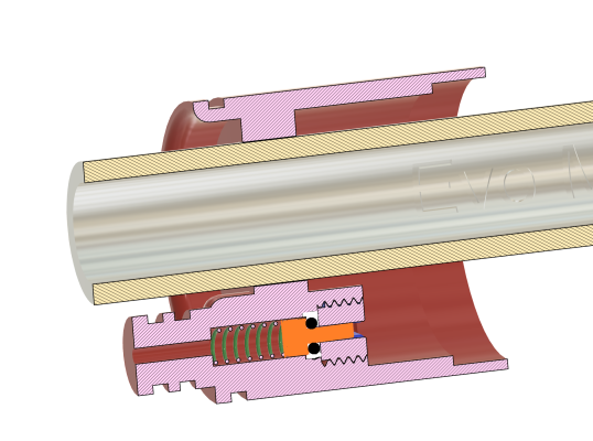
You have drawn the internal volume of the receiver in blue! Is it water or air?When you have a finished speargun in front of you where everything works as it should, you don't even think about the fact that someone went to great lengths to make it that way.
I had to look up this sketch to remind myself how it works...
View attachment 60762
-
Welcome to the DeeperBlue.com Forums, the largest online community dedicated to Freediving, Scuba Diving and Spearfishing. To gain full access to the DeeperBlue.com Forums you must register for a free account. As a registered member you will be able to:
- Join over 44,280+ fellow diving enthusiasts from around the world on this forum
- Participate in and browse from over 516,210+ posts.
- Communicate privately with other divers from around the world.
- Post your own photos or view from 7,441+ user submitted images.
- All this and much more...
You can gain access to all this absolutely free when you register for an account, so sign up today!
GeckoSub Mirage Evo - And Adventures in 3D Printing Speargun Parts
- Thread starterDiving Gecko
- Start date
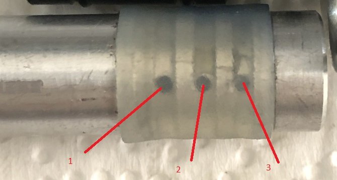
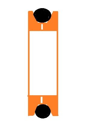
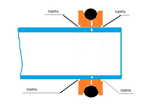
You can't make a valve like that! These are three separate valves! The probability of failure is three times higher! Valve #2 doesn't work at all! Only 1 and 3 work! The correct valve must be made according to this scheme! There are several holes in the groove and one O-ring in a trapezoidal groove! The diameter of the holes is no more than 1 mm! An unloaded barrel can be drilled with 8 holes of 1 mm each! This will be enough for loading without throttling! For soldering, it is better to take a barrel made of stainless steel and make the valve sleeve from brass or stainless steel!
Attachments
Last edited:
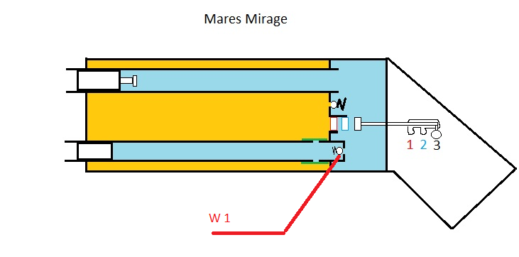
Zahar, all inside the sketch is air, blue and orange..You have drawn the internal volume of the receiver in blue! Is it water or air?
David, Zahar is right about the first image.There is not necessary three holes in line. The middle one would be sufficient, having two holes symmetrically..
About the little black shards you found. Did you lubricate the parts that are rubbing? The inlet for the power regulator O-ring might need to be beveled to a smaller angle, maybe 30 degrees.. I don't know what yours is..
Last edited:
You can't make a valve like that! These are three separate valves! The probability of failure is three times higher! Valve #2 doesn't work at all! Only 1 and 3 work! The correct valve must be made according to this scheme! There are several holes in the groove and one O-ring in a trapezoidal groove! The diameter of the holes is no more than 1 mm! An unloaded barrel can be drilled with 8 holes of 1 mm each! This will be enough for loading without throttling! For soldering, it is better to take a barrel made of stainless steel and make the valve sleeve from brass or stainless steel!
Can You Please Go Easy With The Dogmas?
Let's establish some house rules. I don't respond well to dogmatic people yelling. Which is how your exagerrated use of exclamation marks and dogmatic statement sound like. So, if you want me to read your post and take you seriously, I suggest you dial this down.
In the case of this valve, literally 1000s of guns have been made with them. This is the valve used on every original Mirage gun ever made. You may not know this but that's fact.
Your proposed valve may work better in theory, but in practice this method has worked for close to 50 years. Mirages may leak in several places but this is not a common one.
That said, I made a few small changes to the original design which may actually be the reason for my leak. But it sounds strange when you dogmatically state that a valve that has worked for 50 years "can't be made like this".
It also doesn't help that whatever translation you are using is not doing a great job. The bad translation and the seeming lack of accepting that there are many ways to skin a cat reminds me of another person on this thread that I stopped engaging with.
E.g. you start talking about stainless barrels and soldering (welding?). Why?
I have a set of constraints clearly explained in this thread which is to use a stock Salvimar barrel, so of course there will not be any stainless barrel here. I have also often talked about like my guns to be neutrally buoyant so I will not be making any barrels out of stainless. I long ago gathered that neutral guns is not a big thing in your region but it is to me.
On a different gun, maybe a longer gun or one with a reservoir with more volume, perhaps I will look into stainless or titanium barrels. Still, I don't want to get into welding anytime soon.
Last edited:
You have golden hands, but little knowledge on the operation and use of valve systems! I tried to help you with this gap! I do not tolerate hypocrisy and comparisons with Vlanik! I counted on gratitude, but in return I received a reproach! Follow the course of the Russian ship!Can You Please Go Easy With The Dogmas?
Let's establish some house rules. I don't respond well to dogmatic people yelling. Which is how your exagerrated use of exclamation marks and dogmatic statement sound like. So, if you want me to read your post and take you seriously, I suggest you dial this down.
In the case of this valve, literally 1000s of guns have been made with them. This is the valve used on every original Mirage gun ever made. You may not know this but that's fact.
Your proposed valve may work better in theory, but in practice this method has worked for close to 50 years. Mirages may leak in several places but this is not a common one.
That said, I made a few small changes to the original design which may actually be the reason for my leak. But it sounds strange when you dogmatically state that a valve that has worked for 50 years "can't be made like this".
It also doesn't help that whatever translation you are using is not doing a great job. The bad translation and the seeming lack of accepting that there are many ways to skin a cat reminds me of another person on this thread that I stopped engaging with.
E.g. you start talking about stainless barrels and soldering (welding?). Why?
I have a set of constraints clearly explained in this thread which is to use a stock Salvimar barrel, so of course there will not be any stainless barrel here. I have also often talked about like my guns to be neutrally buoyant so I will not be making any barrels out of stainless. I long ago gathered that neutral guns is not a big thing in your region but it is to me.
On a different gun, maybe a longer gun or one with a reservoir with more volume, perhaps I will look into stainless or titanium barrels. Still, I don't want to get into welding anytime soon.
I (May) Have Found The Problem
The rubber sleeve valve I made is based on the original one Mares put in 1000s(?) of Mirages and while that gun did have issues, I haven't heard of the valve being one of them. So, I decided to go with that for the sake of simplicity.
The orginal Mares valve is made this way: 3 rows of holes, 4 on each row, 12 in total. Maybe that's too many, but it has seemingly worked for decades. I long ago took precise measurements of the geometry of it for another Mirage that I extended and which worked. But I can't recall the size of the holes. I feel like they were tiny, maybe just 1.00mm like Zahar mentions as a good size for his different type of valve.
Anyways, please stay tuned for the conclusion, but first let's look at today's findings after I took the gun apart again:
The Findings
I inspected everything and at first glance, it looked OK. The bulkhead hadn't shifted, no torn o-rings, no debris. Actually, I had ruled out a leak in the bulkhead even before opening the gun today as the gun had held a pressure differential overnight between the two chambers of about about 8 bars. If there had been a leak in the power regulator bushing or the bulkhead o-rings, then the pressure would have been equalized. Also, the fact that the I did manage to "move" 8 bar of air before the pumping mech stopped working led me to believe either the check valve or the rubber sleeve valve could be the issue.
I hooked my vacuum pump up to the pumping barrel and check valve:

And this revealed a leak in the rubber sleeve valve. Actually, one of the holes in the valve had pierced a hole in the rubber sleeve and the sleeve was knicked in two other places as well. But I didn't catch it on the visual inspection as it was tiny.
It's only clear here because the screwdriver enlarged the hole. Also, if you look to the left of the screwdriver you see a shiny spot - that's how the hole looked (not easy to spot):

So, while I will uphold the opinion that the original Mares design of this valve is not to blame, I made two changes that could explain this failure mode:
- First off, I made the holes bigger. As I said, I can't exactly remember how small the original ones are but I think 1.0mm and I made them 1.5mm. At 30bar, that increases the force on the rubber over each of those holes from 0.24kgf to 0.54kgf. Which leads me to the second part of this suspected failure mode:
- I know I say "rubber valves". And Mares actually used a stiffer rubber for these valves whereas I switched to silicone tubing. Silicone is what I had and I even turned down the OD on the lathe. First of all, silicone is famous for tearing quite easily which I knew and why I deburred the holes as well as I thought I needed to but what I also missed was that it has worse resistance to petroleum based products or synthetic esters which is often what fork oil that I used in my guns are made up from (according to chatgpt).
So, here's the scenario that I tentatively conclude caused the failure:
The silecone sleeve got pushed into bigger than original holes when I started pumping and it got punctured. This is why I could move some air and then suddenly it felt like I was just puming against the same, high pressure stroke after stroke.
Whether the oil in the fork had already degraded the silicone enough to speed this up, I don't know or perhaps the machining of the OD weakened it.
What I have done now:
I have deburred the holes and grooves even more. Ended up polishing with a diamond paste:

What Is Still To Be Done
I will order real rubber sleeve but it will take a while to get here. So, in the meantime, I will do less pre-pumps which will result in less pressure differential between the two chambers, less of an increase in the front chamber and thus less force on the silicone. But also, less drop of pressure in the rear chamber and thus a less easy time for final cocking in the shooting barrel. If this doesn't work, I may whip up a new pumping barrel with tiny holes - or a real check valve.
On The Plus Side
IF my findings and conclusions above are correct it means my bulkhead, power regulator and check valve works as intended which would be nice")
The rubber sleeve valve I made is based on the original one Mares put in 1000s(?) of Mirages and while that gun did have issues, I haven't heard of the valve being one of them. So, I decided to go with that for the sake of simplicity.
The orginal Mares valve is made this way: 3 rows of holes, 4 on each row, 12 in total. Maybe that's too many, but it has seemingly worked for decades. I long ago took precise measurements of the geometry of it for another Mirage that I extended and which worked. But I can't recall the size of the holes. I feel like they were tiny, maybe just 1.00mm like Zahar mentions as a good size for his different type of valve.
Anyways, please stay tuned for the conclusion, but first let's look at today's findings after I took the gun apart again:
The Findings
I inspected everything and at first glance, it looked OK. The bulkhead hadn't shifted, no torn o-rings, no debris. Actually, I had ruled out a leak in the bulkhead even before opening the gun today as the gun had held a pressure differential overnight between the two chambers of about about 8 bars. If there had been a leak in the power regulator bushing or the bulkhead o-rings, then the pressure would have been equalized. Also, the fact that the I did manage to "move" 8 bar of air before the pumping mech stopped working led me to believe either the check valve or the rubber sleeve valve could be the issue.
I hooked my vacuum pump up to the pumping barrel and check valve:

And this revealed a leak in the rubber sleeve valve. Actually, one of the holes in the valve had pierced a hole in the rubber sleeve and the sleeve was knicked in two other places as well. But I didn't catch it on the visual inspection as it was tiny.
It's only clear here because the screwdriver enlarged the hole. Also, if you look to the left of the screwdriver you see a shiny spot - that's how the hole looked (not easy to spot):

So, while I will uphold the opinion that the original Mares design of this valve is not to blame, I made two changes that could explain this failure mode:
- First off, I made the holes bigger. As I said, I can't exactly remember how small the original ones are but I think 1.0mm and I made them 1.5mm. At 30bar, that increases the force on the rubber over each of those holes from 0.24kgf to 0.54kgf. Which leads me to the second part of this suspected failure mode:
- I know I say "rubber valves". And Mares actually used a stiffer rubber for these valves whereas I switched to silicone tubing. Silicone is what I had and I even turned down the OD on the lathe. First of all, silicone is famous for tearing quite easily which I knew and why I deburred the holes as well as I thought I needed to but what I also missed was that it has worse resistance to petroleum based products or synthetic esters which is often what fork oil that I used in my guns are made up from (according to chatgpt).
So, here's the scenario that I tentatively conclude caused the failure:
The silecone sleeve got pushed into bigger than original holes when I started pumping and it got punctured. This is why I could move some air and then suddenly it felt like I was just puming against the same, high pressure stroke after stroke.
Whether the oil in the fork had already degraded the silicone enough to speed this up, I don't know or perhaps the machining of the OD weakened it.
What I have done now:
I have deburred the holes and grooves even more. Ended up polishing with a diamond paste:

What Is Still To Be Done
I will order real rubber sleeve but it will take a while to get here. So, in the meantime, I will do less pre-pumps which will result in less pressure differential between the two chambers, less of an increase in the front chamber and thus less force on the silicone. But also, less drop of pressure in the rear chamber and thus a less easy time for final cocking in the shooting barrel. If this doesn't work, I may whip up a new pumping barrel with tiny holes - or a real check valve.
On The Plus Side
IF my findings and conclusions above are correct it means my bulkhead, power regulator and check valve works as intended which would be nice
Last edited:
Zahar, I apologise for being snide and I am actually very glad that you think V is an unfair comparison.You have golden hands, but little knowledge on the operation and use of valve systems! I tried to help you with this gap! I do not tolerate hypocrisy and comparisons with Vlanik! I counted on gratitude, but in return I received a reproach! Follow the course of the Russian ship!
But please understand that when you use exclamation marks as much as you do, it reads like you are screaming at us.
And also, please understand that the design of the valve that you said "can not be made like this" has been used in probably 1000s of mass produced guns and as far as I know those valves have worked well enough.
I don't doubt there are better valves out there which is something I would like to incorporate in the future. But when something has worked for decades and is simple and fast to make, then sometimes that is a good enough approach.
Lastly, while your proposed valve may be better, I don't think I would have the space for it. My constraints are a 38mm ID reservoir, a OD 18mm shooting barrel and a OD 13mm pumping barrel. Which means I have ~1.2mm space around the pumping barrel to fit a valve onto. Another check valve inside the end of the pumping barrel could work, but I wanted to do this the simple, proven way.
Now, if you accept my apology, please read the post about what I think I did wrong when using this type of valve. It's actually more about the execution and material choice than the basic design of the valve.
Last edited:
Zahar, all inside the sketch is air, blue and orange..
David, Zahar is right about the first image.There is not necessary three holes in line. The middle one would be sufficient, having two holes symmetrically..
About the little black shards you found. Did you lubricate the parts that are rubbing? The inlet for the power regulator O-ring might need to be beveled to a smaller angle, maybe 30 degrees.. I don't know what yours is..
As for all the holes, I just did it as Mares did all those years ago. Which of course doesn't mean it's the correct way. But as far as I know, people haven't complained about that valve in the Mirages. Other leaks, yes, but not the valve. (I could of course be wrong on this).
I did always wonder why Mares felt so many holes were needed. Partly, I realized today - as you see from the suspected failure mode outlined above - is to be able to make each hole much smaller so there's less risk of the rubber being pushed into the hole and getting pierced. But 12 is perhaps still too many.
If we assume that the original Mares holes were Ø1mm, then 12 of them equals one hole of about Ø3.5mm. That's likely still a lot for a 10mm piston.
As for the debris. I am almost 100% sure it was from the pumping piston and the rear o-ring on the pumping piston as both showed signs of being chewed up. No other o-rings were harmed
. And I am happy to report that the fixed I made for those two issues seem to have worked as in the latest disassembly the piston front and rear o-ring looked in great condition.On that same note of o-rings not being cut, I just have 45D chamfers - as wide as I can make them though - everywhere. But that's just because my chamfer tool is a 90D one - maybe I should look for some 60D ones...
I completely understand you. I've been through similar problems myself. Almost always something needs to be modified, tweaked. The hardest part is pinpointing the problem. Sometimes more than one thing needs to be corrected. I don't know if you copied key parts from an existing Mirage rifle. I'm thinking of valve diameters, O-ring sizes, valve spring lengths, diameters, and strengths... Someone must have taken the trouble to bring it all into proper harmony. Small deviations are enough to cause unexpected problems.
"Small deviations are enough to cause unexpected problems" - Exactly this Tomi.
I thought I stuck close to the original but I made the holes bigger and used a way softer tubing material. That's what I think caused the failure. (I will know in a few days but it's what makes the most sense right now)
Last edited:
My manner of putting exclamation marks at the end of a sentence should not confuse you, just like Einstein's protruding tongue in the photo! This is done to identify my messages and for convenience when working on a laptop keyboard! I do not put an exclamation mark only in obituaries!
Regarding the valve: 1. The silicone hose is too soft and is pressed into the holes; 2. Silicone does not hold air pressure well, this was tested on RPS 3 barrels; 3. The total area of the transverse holes, 8 pcs., 1 mm each, is sufficient in manual loading mode in terms of loading time without significant resistance to throttling; 4.
The three-row arrangement of the holes increases the size of the piston; 5. The valve, which blocks the access of receiver pressure to the barrel during the piston stroke, opens when the piston stops and again pushes the piston to its original position;
Attachments

My manner of putting exclamation marks at the end of a sentence should not confuse you, just like Einstein's protruding tongue in the photo! This is done to identify my messages and for convenience when working on a laptop keyboard! I do not put an exclamation mark only in obituaries!
Regarding the valve: 1. The silicone hose is too soft and is pressed into the holes; 2. Silicone does not hold air pressure well, this was tested on RPS 3 barrels; 3. The total area of the transverse holes, 8 pcs., 1 mm each, is sufficient in manual loading mode in terms of loading time without significant resistance to throttling; 4.
The three-row arrangement of the holes increases the size of the piston; 5. The valve, which blocks the access of receiver pressure to the barrel during the piston stroke, opens when the piston stops and again pushes the piston to its original position;
Yes, the silicone gets pushed into the holes and gets cut. I think that's exactly what happens. Especially as I made the holes bigger
I actually think - or hope - the rest of my parts work as they should. But I will know on Sunday when we go spearing again.
I will make the next pumping barrel with 1mm holes and just 8 of them. It makes sense that it should be enough. For now, I just hope the silicone lasts until I get the real rubber which also tears less easily. For now, I changed to a silicone that's a little bit thicker, polished the holes some more and if I pump less perhaps it will survive.
Thanks for clarifying your use of exclamation mark, I understand now and also that they shouldn't be used in obituaries
.David last time when I worked on my Mirage, near 10 years ago.., for rubber valve I used the Sten 11 shock absorber damping rubber.As for all the holes, I just did it as Mares did all those years ago. Which of course doesn't mean it's the correct way. But as far as I know, people haven't complained about that valve in the Mirages. Other leaks, yes, but not the valve. (I could of course be wrong on this).
I did always wonder why Mares felt so many holes were needed. Partly, I realized today - as you see from the suspected failure mode outlined above - is to be able to make each hole much smaller so there's less risk of the rubber being pushed into the hole and getting pierced. But 12 is perhaps still too many.
If we assume that the original Mares holes were Ø1mm, then 12 of them equals one hole of about Ø3.5mm. That's likely still a lot for a 10mm piston.
As for the debris. I am almost 100% sure it was from the pumping piston and the rear o-ring on the pumping piston as both showed signs of being chewed up. No other o-rings were harmed
On that same note of o-rings not being cut, I just have 45D chamfers - as wide as I can make them though - everywhere. But that's just because my chamfer tool is a 90D one - maybe I should look for some 60D ones...
"Small deviations are enough to cause unexpected problems" - Exactly this Tomi.
I thought I stuck close to the original but I made the holes bigger and used a way softer tubing material. That's what I think caused the failure. (I will know in a few days but it's what makes the most sense right now)
I have no image of the pumping barrel without the rubber so I forgot how it was acctualy loking, how many holes it had.

Thanks for the drawing Zahar.I might try that on the next bulkhead.Ball valves are unreliable! It is better to use a mushroom valve!
Only compression on the o-ring in the axial direction (red arrows), right?
The blue arrows is oversized free space, right?

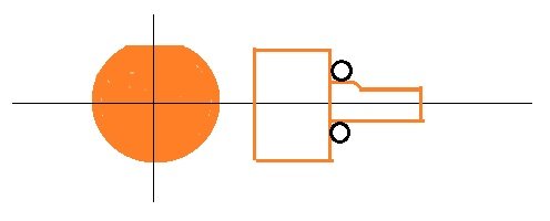
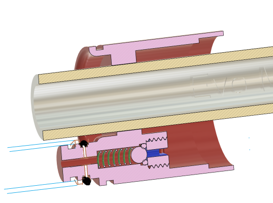
Is it better, more clear, this way...?There must be space! The diameter of the large valve must be larger than the diameter of the O-ring! Milling must be done on the large diameter of the valve!

Yes, thanks for clarifying.There must be space! The diameter of the large valve must be larger than the diameter of the O-ring! Milling must be done on the large diameter of the valve!
In my own o-ring groove designs I always leave "free space" and only ever compress in one direction.
On that same note, I have found instances in both the Predathor and this Mares handle where the engineers thought it was ok to compress the o-ring on all sides...
A Small Correction
Honestly, even I have lost track of what I have put in this very, very long build thread, so it may be in there already but I may have forgotten. But it turns out that even though I call this a Mirage Evo gun based on it being a Mirage system with a Mares (Cyrano) Evo handle, I am actually not using an Evo handle...
I wouldn't be surprised it Pete pointed that out long ago and if he did, my apologies, I may just have stuck with the name by then. Anyways, the handle I am using is a Cyrano 1.3 handle. Not that I can really recommend going down this path. If it was as "easy" as I thought it would be, then this thread wouldn't be +20 pages
Honestly, even I have lost track of what I have put in this very, very long build thread, so it may be in there already but I may have forgotten. But it turns out that even though I call this a Mirage Evo gun based on it being a Mirage system with a Mares (Cyrano) Evo handle, I am actually not using an Evo handle...
I wouldn't be surprised it Pete pointed that out long ago and if he did, my apologies, I may just have stuck with the name by then. Anyways, the handle I am using is a Cyrano 1.3 handle
. Not that I can really recommend going down this path. If it was as "easy" as I thought it would be, then this thread wouldn't be +20 pagesHurray, A 3D-printed Part...
The title of this thread alludes to a lot of 3D printing but honestly, there's no longer any major or important 3D-printed parts on the gun. But did make a small one today so we should celebrate a small victory like this! haha.
Didn't get much done on the gun today but did manage to track down a used refrigerator compresssor pump and a butane torch for soldering the pneumatic fittings to the new pump. Though I only bought the butnae torch and hour ago and not knowing whether I would, I have already glued them on with the strongest loctite I have... Either way, I should be able to use the pump to fill the gun tomorrow and not have to ask the scuba shops for air anylonger
Also, another spearfishing session tomorrow afternoon and since it's a shore diving session I will only bring one gun, so I really hope the system will work now.
Anyhow, back to the 3D print: The modified handle is still rough in places and since I no longer use wetsuit socks in my foot pockets I had three skin abrasions on my left foot from loading during the pool session. They weren't bad, but when you live in the tropics and drive your scooter in flip flops, even small cuts get infected so now, it's far from pretty.
So, I made a rounded 3D printed valve plug and later on rounded the edges of the handle a bit more. It feels a whole lot better:


I may find an oversized old wetsuit sock, cut it down and use it as a sleeve over the top of my foot for a bit of padding, too.
Last edited:
Just to confirm, the flats on the "mushroom head" and the stem are to make an airpath, right?