• Welcome to the DeeperBlue.com Forums, the largest online community dedicated to Freediving, Scuba Diving and Spearfishing. To gain full access to the DeeperBlue.com Forums you must register for a free account. As a registered member you will be able to:

    • Join over 44,280+ fellow diving enthusiasts from around the world on this forum
    • Participate in and browse from over 516,210+ posts.
    • Communicate privately with other divers from around the world.
    • Post your own photos or view from 7,441+ user submitted images.
    • All this and much more...

    You can gain access to all this absolutely free when you register for an account, so sign up today!

GeckoSub Mirage Evo - And Adventures in 3D Printing Speargun Parts

There must be space! The diameter of the large valve must be larger than the diameter of the O-ring! Milling must be done on the large diameter of the valve!

Hi Zahar, I didn't notice this drawing until now but I really like this solution, too. It's very simple and compact. And it also means, I don't need to find and keep rubber tubing for this purpose but only o-rings.

When I make the next bulkhead, I think I will use your two latest ideas - but I will post my drawings before I do any machining to confirm I am on the right path. It will take a little while though.
But thanks again.
Screenshot 2025-03-16 at 14.15.27.png
 
  • Like
Reactions: Zahar
Couldn't Help It...
It's Sunday and I was supposed to only watch F1 and then do nothing else (we cancelled spearing today). But I had to draw up some sketches... Well, I didn't have to, but I did.

The first one is just an overview of how the barrels are in relation to each other:
EVO_MIRAGE_2025_9005_750pix.JPG

In the next, close up one I changed to a 60d chamfer tool, so the angles for the groove side walls are 30d each (45d on the first pic). And I am keeping the o-ring a bit higher in the groove (the o-ring is 2.5mm cross section, the venting bore is 1mm):
EVO_MIRAGE_2025_9008_750pix.JPG


And in this one, the o-ring is allowed to sit deeper in the groove and press directly against the venting bores:
EVO_MIRAGE_2025_9009_750pix.JPG


Zahar which one do you prefer? Would you make it so that the o-ring touches the venting bores? Or best to only/mostly seal against the chamfered sides? I think I prefer the latter, but I have never made a valve like this before.
 
Zahar which one do you prefer? Would you make it so that the o-ring touches the venting bores? Or best to only/mostly seal against the chamfered sides? I think I prefer the latter, but I have never made a valve like this before. -----------------------------------------A flatter trapezoid angle in the groove allows for a thicker O-ring! In both cases, the O-ring will be pressed against the hole by the receiver pressure! By trial and error and with the help of a vacuum pump, you can select the optimal O-ring for any trapezoid angle! In fact, there is no great pressure load on this valve from the receiver! The pressure of the O-ring on the holes is determined mainly by the tension of the O-ring in the trapezoid!
 
Last edited:
  • Like
Reactions: Diving Gecko
Zahar which one do you prefer? Would you make it so that the o-ring touches the venting bores? Or best to only/mostly seal against the chamfered sides? I think I prefer the latter, but I have never made a valve like this before. -----------------------------------------A flatter trapezoid angle in the groove allows for a thicker O-ring! In both cases, the O-ring will be pressed against the hole by the receiver pressure! By trial and error and with the help of a vacuum pump, you can select the optimal O-ring for any trapezoid angle! In fact, there is no great pressure load on this valve from the receiver! The pressure of the O-ring on the holes is determined mainly by the tension of the O-ring in the trapezoid!

Actually, that's a good point, instead of making a full bulkhead, I can make some small test parts first to get the geometry of this valve dialed in.
 
  • Like
Reactions: Zahar
The pressure P 1 will be less than the pressure P by the amount of the spring force F!
 

Attachments

  • Screenshot 2025-03-16 at 14.15.27.png
    Screenshot 2025-03-16 at 14.15.27.png
    466 KB · Views: 21
  • Like
Reactions: Diving Gecko
The pressure P 1 will be less than the pressure P by the amount of the spring force F!
Yes, true.
I tried to calculate this out the other day but now I think I may have done it the wrong way.
I measured the spring force to crack open the valve on a weighing scale but I also included the force on the valve from the pressure.

The spring force itself is low, just 200-300g on the scale, so I guess 0.2-0.3kgf(?). The surface area of the valve that the pressure acts against is about 7mm2. But the pumping barrel is almost "empty" at the end of a pumping stroke with not much pressure in it, so I think I was wrong including the gun's pressure in that calculation. So, in practical terms, the valve will actually open very easily, without much resistance to refill the pumping barrel.
 
Last edited:
  • Like
Reactions: Zahar
The trapezoid groove valve has another application! For pneumatic vacuum guns in the pneumatic vacuum cuff breakage mode! The emergency valve allows you to fire even with water in the barrel!
 

Attachments

  • Клапан для ПВ надульника 123.jpg
    Клапан для ПВ надульника 123.jpg
    139.6 KB · Views: 25
Yes, true.
I tried to calculate this out the other day but now I think I may have done it the wrong way.
I measured the spring force to crack open the valve on a weighing scale but I also included the force on the valve from the pressure.

The spring force itself is low, just 200-300g on the scale, so I guess 0.2-0.3kgf(?). The surface area of the valve that the pressure acts against is about 7mm2. But the pumping barrel is almost "empty" at the end of a pumping stroke with not much pressure in it, so I think I was wrong including the gun's pressure in that calculation. So, in practical terms, the valve will actually open very easily, without much resistance to refill the pumping barrel.
This is another reason to abandon the ball valve! The ball swings like a hinge and the difference P - P1 is small for reliable pressing of the O-ring!
 
The trapezoid groove valve has another application! For pneumatic vacuum guns in the pneumatic vacuum cuff breakage mode! The emergency valve allows you to fire even with water in the barrel!
That sounds like a good idea. Normally, people only realize the vacuum cuff is broken because they see a big loss in power and a squirt of water out the front when shooting. A release valve like this may just be enough to save the gun from having water pushed behind the piston seals.
 
  • Like
Reactions: tromic
That sounds like a good idea. Normally, people only realize the vacuum cuff is broken because they see a big loss in power and a squirt of water out the front when shooting. A release valve like this may just be enough to save the gun from having water pushed behind the piston seals.
That's right! And when shooting with water in the barrel, the valve does not provide much resistance to the water exiting the barrel!
 
  • Like
Reactions: Diving Gecko
I hope that when you finish this gun, you will have the desire to make a gun according to my scheme with a vacuum pump! Your experience allows you to move on!
 
  • Like
Reactions: Diving Gecko
I hope that when you finish this gun, you will have the desire to make a gun according to my scheme with a vacuum pump! Your experience allows you to move on!
I do have plans to make a more Mirage type guns and I hope to make the whole handle from scratch, too as there are some improvements I think I can add there.
I may even make my own vacuum muzzle or at least shooting barrel pistons next time in which case, the only thing that will be stock on those guns is the shooting barrel unless I find some titanium barrels I can use - or manage to keep the rest of the gun so light that I can still make it neutral with a stainless shooting barrel.

I have already designed the handle and even a new trigger. And I test cut a sear on my machine to see if I could mill hardened 440C steel and I could - it just takes a very long time, but that's OK.

The bigger issue is that I need more practice on my machine to figure out how to cut really deep features, like into a handle and also, some of the work holding is a bit tricky. But I think I may be able to pull this off.
A few things that I think will help is that I have designed the handled to be as short as it can be and also, I am tapering the inside walls. The latter should help a lot as the cutter wont be rubbing when it's deeper in the cut. And even then, if I get a little bit of chatter, it will be on the inside walls so it should be OK.

But I don't think I will have time to work on that project until maybe late summer or autumn as I have another big (freedive related) project I need to finish before then.
 
Last edited:
Yes, true.
I tried to calculate this out the other day but now I think I may have done it the wrong way.
I measured the spring force to crack open the valve on a weighing scale but I also included the force on the valve from the pressure.

The spring force itself is low, just 200-300g on the scale, so I guess 0.2-0.3kgf(?). The surface area of the valve that the pressure acts against is about 7mm2. But the pumping barrel is almost "empty" at the end of a pumping stroke with not much pressure in it, so I think I was wrong including the gun's pressure in that calculation. So, in practical terms, the valve will actually open very easily, without much resistance to refill the pumping barrel.

I am confusing myself (again). I actually was on the right path the first time around;)
To crack open a valve that has a spring with a spring force of ~0.3kgf and a surface area of 7.1mm2 (3mm diameter) would take a pressure differential of ~4 bar. (I think I said 7bar last time for a weaker 200gf spring but there was an error in the spreadsheet I use for these things)

I guess this in theory means I could move enough air to the front chamber that the final loading effort would only be against ~4 bar in the rear chamber (not counting piston friction and such). It also means, I can go up a bit in spring force if I want to.

The numbers below are after I caught the error in the spreadsheet:
Screenshot 2025-03-16 at 23.04.09.png
 
Last edited:
  • Like
Reactions: Zahar
I do have plans to make a few more Mirage type guns again - where I make the whole handle from scratch, too:). I may also make my own vacuum muzzle next time in which case, the only thing that will be stock on those guns is the shooting barrel unless I find some titanium barrels I can use - or manage to keep the rest of the gun so light that I can make it neutral with a stainless shooting barrel.

I have already designed the handle and even a new trigger and test cut the sear on my machine to see if I could mill hardened steel and I could - it just takes a very long time, but that's OK:)

But I don't think I will have time to work on that project until maybe late summer as I have another big (freedive related) project I need to finish before then.

The spring force can be increased but only up to a certain limit! This limit is the vacuum force during the piston return stroke! Again, it is necessary to use a vacuum pump for control!
 
One More (Little) Setback
I got my hands on a secondhand compressor so I can now pump the gun easily in the workshop. So, I took the gun up to 28 bar to test the pumping mechanism and it seemed the silicone sleeve valve on the pumping barrel was surviving. I had changed to a tubing with a slightly thicker wall and also polished the venting bores even more. But... then after a few tests of the pumping feature, it stopped working again!

So, I took the gun apart - easier mentally when you know it's easy to pump back up again;). And the sleeve looked fine. No holes in it this time.

A bit more disassembly revealed this though:
EVO_MIRAGE_2025_3803_750pix.JPG


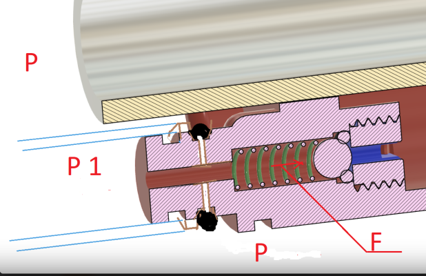
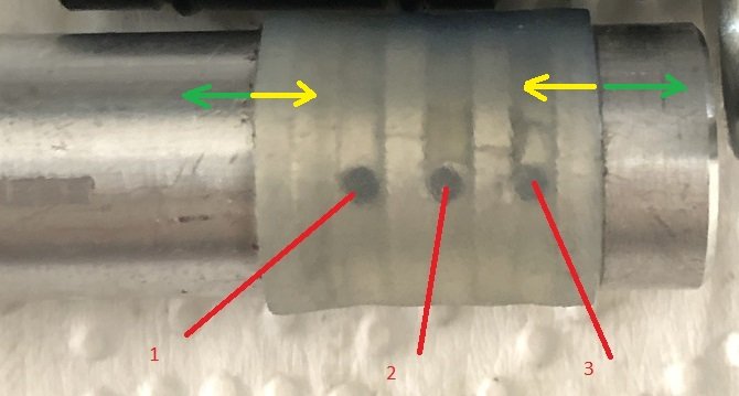
The o-ring on the power regulator bushing had split in half. This corresponds to me feeling that on the last failed round of tests, it was surprisingly harder to close the valve. The bore was chamfered as much as the geometry allowed it during the machining and then deburred with the grinder. But I went over it again:
EVO_MIRAGE_2025_3806_750pix.JPG


Also spent a fair bit of time with diamond polishing pastes:
EVO_MIRAGE_2025_3808_750pix.JPG


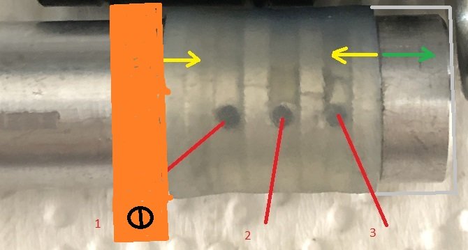
And smoothed the edges on the bushing, too:
EVO_MIRAGE_2025_3810_750pix.JPG


When I assembled it again, there was a notable difference - the bushing inserts into the bore a whole lot easier now, so I hope this will solve the problem. It's designed for 25-27% compression so I think that part of the design is fine, just that there must have been a sharp edge that needed more rounding.

I know this is a little weird, but I think it's very fitting that I am using a Nikonos grease for this gun;). The Nikonos V underwater camera launched in 1984 and I'll have to look it up but I think the Mirage must have been around the same time.
EVO_MIRAGE_2025_3814_750pix.JPG


I am using an o-ring as a spacer between the two barrels to get the spacing correct and another one to hold them together - this helps when I try to line up and slide the nose cone on during assembly:
EVO_MIRAGE_2025_3821_750pix.JPG

I have drawn up a simple little bracket to do the same job. I may machine that some day but it's not a priority right now.

So, after this most recent, hopefully succesful fix, I took the gun back up to ~28 bar:
EVO_MIRAGE_2025_3798_750pix.JPG


Then five pre-loading pump strokes and the pressure dropped to ~7 bar:
EVO_MIRAGE_2025_3802_750pix.JPG


With four pumping strokes it drops to ~10 bar. I think that's pretty good territory to be in. Doesn't take long to do 4-5 strokes and cocking in the shooting barrel at 7-10 bar is easy:).

I went on to open the power regulator and then close it and do the pumping sequence again three times in total and nothing has broken so far. Last two times around, when the silicone sleeve got punctured both times it happened the first time I opened the valve. The power regulator closes easily too, now so maybe we are finally in the clear.

We may go spearing tomorrow, so that will be the real world test.

Finally, I also whipped together a new loader with a short extension:
EVO_MIRAGE_2025_3833_750pix.JPG

Alu for the top whilst the lower handle is carbon, only for the simple reason that I had some;). The line is dyneema and then I have a bungee on it, too so I can easily put my hand through it and let it sit above my elbow when not in use.
 
Last edited:
  • Like
Reactions: tromic
A Few More 3D-printed Parts
This whole build log was supposed to be about 3D-printing parts for a speargun but I have strayed from that path. But here are a few prints, maybe just enough that the title of this build log wont be such a complete mismatch anylonger;)

I forgot I had designed and printed a custom trigger long ago. It solved two issues:
It reduces the distance to the trigger and the plastic slides way, way easier on the stainless steel line release (the original stainless on stainless had horrible friction).
EVO_MIRAGE_2025_3817_750pix.JPG

EVO_MIRAGE_2025_3838_750pix.JPG


And as "always" I do like to put fiber optic sights on my guns, so here's a holder for such one:
EVO_MIRAGE_2025_3827_750pix.JPG


So, in the end, I think we are down to only three 3D-printed parts - the third being the plug for the inlet valve. Reposting a pic here:
EVO_MIRAGE_2025_3789_750pix.JPG


In the first itiration of this gun, the bulkhead and nose cone - properly important parts - were printed and I do think this is doable in resin, but since I now have a CNC capable of machining alu, I wanted to go with that. It's heavier, yeah, but it holds great tolerances and of course the strength is there.

What's Next?
If the gun actually works as intended now, I may still make a few improvements - mostly to do with losing weight. Ideally, I'd like to get it close to neutral and then add a reel, too.
I have one left over long carbon reservoir I could cut down and dedicate to this gun and then I could turn down the OD on both the shooting and pumping barrels and also lose some weight from the nose cone or perhaps maybe even try machining a Delrin version. Those changes combined should get me some handy weight savings.

If I really find the time, which is very uncertain, I will finally test front-tied shafts vs. shafts with sliders. For the Mirage system, a front-tied shaft would have the specific advantage that the pumping barrel ID could be reduced for the same size of shaft. The bigger a difference in diameter between the shooting barrel and pumping barrel, the larger the "Mirage effect" becomes. You can use that fact to have an even easier to load gun with the same power or an even more powerful gun that's the same effort to load - or anywhere in between.
 
Last edited:
  • Like
Reactions: tromic
This Is Crazy...
I am not superstitious at all but this is getting too much. This is the 3rd time the gun works great on land and as soon as I load it in the water, the pumping feature stops working...!;(
First time was in the pool test, so I dropped the pressure to "normal". Second time was on the boat dive where I just grabbed the bandgun instead. This time it was a shore dive so I only had this gun with me but at least I figured out that I can open the inlet valve and drop the pressure using my dive knife.

Here I am aiming at a coral trout (best eating around here) but while they are easy to get almost everywhere else I have seen them (Thailand and Indo), here they are almost as smart as groupers. I think had this been a few years back when I was diving often and really trusted my aim I would have taken the shot but I didn't. So, maybe I will get him another day;)
EVO_MIRAGE_2025_9011_750pix.JPG


So, no fish this day - my island sees a lot of pressure and the fish are very smart and I am bit out of practice. Good training and good exercise, though so not in vein.

Today, I opened the gun once again, this time the o-ring on the power regulator bushing was fine and the silicone sleeve isn't punctured but I think it may just have moved on the barrel and exposed the first row of venting holes. It looked like that when I disassembled the gun but it could have happened during the disassembly, too. What seems almost certain is that the silicone does swell and expand due to the oil in the gun which could explain why it had moved. To confirm this, I dropped some of the tubing in a jar of the same oil and will inspect that tomorrow.

The check valve still seems to work as it should, too. That's pretty much the only thing that seems to have worked the first time around, haha.

Anyways, I will figure this out, just have to keep chipping away at it.

In other news, this thing showed up today:
GECKOSUB_CNC_LATHE_3884_750pix.JPG


A secondhand CNC lathe. Nothing too fancy. E.g. just traditional V-ways and a bit rough around the edges as Chinese cast iron machines often are. But this brand is "famous" for still making sure everything important holds good tolerances and has decent parts E.g. beefy tapered roller bearings, a precision ground spindle, a collet closer and hardened ways. Simple steppers though 3 phase which was supposedly the better choice back when this was made.
It was 107kg as it arrived. I think my manual mini lathe is perhaps 40-45kg and this one is actually a bit shorter. So, way more iron in the castings which is a good thing.
The price was a steal and while I was thinking of putting servos on it, I think I will just clean it up and get a cheap controller for it and start using it before I decide what's really needed in terms of upgrades.

That said, I think it will be another 4-5 months before I really have time to get this project underway. But it will help with making muzzle parts, tail ends for shafts, pistons and I also want to make some slip-tips and maybe some polespear parts, too:)
 
Last edited:
  • Like
Reactions: tromic and Zahar
Silicone does not have a pronounced elastic deformation! Rubber and latex have this! The socket of the silicone tube does not have time to close when the piston stops moving! Then the silicone again takes its dimensions over time! The difference in loading on land and in water can be in the loading time! The slower you load the piston, the less deformation of the silicone and it takes its shape faster! Green arrows - air flow! Yellow arrows - reactive force shifting the hose! The valve usually opens on one side and shifts it! It is necessary to make stops for the hose!
 

Attachments

  • EVO_MIRAGE_2025_3653_800pix.JPG
    EVO_MIRAGE_2025_3653_800pix.JPG
    53.4 KB · Views: 12
  • EVO_MIRAGE_2025_3653_800pix.JPG
    EVO_MIRAGE_2025_3653_800pix.JPG
    52.7 KB · Views: 11
Last edited:
  • Like
Reactions: Diving Gecko
Silicone does not have a pronounced elastic deformation! Rubber and latex have this! The socket of the silicone tube does not have time to close when the piston stops moving! Then the silicone again takes its dimensions over time! The difference in loading on land and in water can be in the loading time! The slower you load the piston, the less deformation of the silicone and it takes its shape faster! Green arrows - air flow! Yellow arrows - reactive force shifting the hose! The valve usually opens on one side and shifts it! It is necessary to make stops for the hose!
Thanks a lot for the analysis:)
I didn't think about how fast or slow it may close compared to real rubber. Come to think about it, I do think I load the gun slower in the workshop that in the water.
But I did suspect that the air flow could be moving the sleeve - in the same way your green arrow shows. And it corresponds to how the sleeve had moved when I inspected it - though there's still the chance it could have happened when I pulled the gun apart.

That said, I also think there's a real risk the oil makes the silicone swell because when I took the sleeve off today it felt a little bit looser already and looser than an unused piece that I compared it to briefly but will investigate that more tomorrow.

I do have a stop on the barrel, but it's possible that it's simply not tall enough. From memory it may just be 0.5mm tall. It's one of the things that was on the list of potential fixes - to make the stop taller. And finally, to add insult to injury in regards to the lower stop - the silicone tube I used on this last try actually has a bigger inner diameter (I think 12mm vs 11mm earlier). So, it's already a little bit less firm around the barrel. But I used it since it has a thicker wall and I was worried about the puncture issue.
 
Last edited:
  • Like
Reactions: tromic and Zahar
DeeperBlue.com - The Worlds Largest Community Dedicated To Freediving, Scuba Diving and Spearfishing

ABOUT US

ISSN 1469-865X | Copyright © 1996 - 2024 deeperblue.net limited.

DeeperBlue.com is the World's Largest Community dedicated to Freediving, Scuba Diving, Ocean Advocacy and Diving Travel.

We've been dedicated to bringing you the freshest news, features and discussions from around the underwater world since 1996.

ADVERT